There a number of write ups for the Prelude cluster but none of them have everything you need in one place. There are several things that need to be changed in order to be functioning correctly and keep the accord's original functions mostly intact. I have an early 90 lx built in 89, late 90-93 are slightly different and since I don't have one I have not been able to 100% verify/test everything for them.
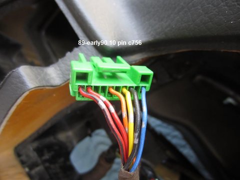
The bottom left C756 connector of the accord cluster is different on 89-mid 90 vs late 90-93. 89-mid 90 has a 10 pin connector and the late 90-93 has 7 pin connector. Either version uses the same 7 wires and colors in the same order just different pin locations.

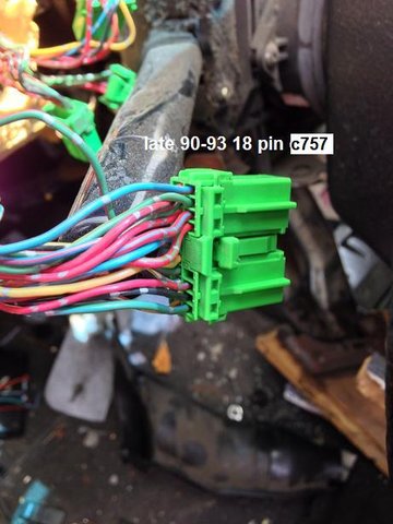
The top c757 connector is also different, 89-early 90 has 16 pins and 92-93 has 18. 89-91 has separate versions for either srs or anti lock each one using the same using indicator location. 92-93 have version have separate indicators locations for abs and srs. The 18 pin is required since a cluster with a full house of indicators needs 17 wires, one more than the 16 pin is capable.

My 90 service manual incorrectly list the terminal numbers in backward order so when comparing with 90 ETM it could cause confusion. Also the ETM has a few mistakes in it. These differences combined with the different connector configurations seem to cause some confusion.
There is also some confusion over Nippon Seiko Vs Nippon Denso clusters. I have found both manufacturers make both connector styles with the exact same wiring. Internally, they are quite different.


Tools Needed
Materials
Cluster Removal
To remove the old cluster is sort of a pain.
Start by removing the console. If you have separate console/ebrake then there are 4 philips screw. If you have attached console/ebrake then there are 6 philips screws. Remove the screws and lift console out of car.
Once center console is out, the radio needs removing. Pull out the ashtray and remove 3 Philips screws holding the carrier. The factory radio is held in with 2 bolts with 8mm heads facing down. Loosen the bolts and slide radio/pocket out to remove.

The dash bezel is held in by 12 screws,
1-behind driver's vent
1-behind coin pocket
1-behind cruise/sunroof switches
1-behind dimmer
2-above cluster
2-behind center vents
2-above radio
2-behind center console

Once the bezel is out remove 4 philips screws holding the cluster in and unplug the 3 connectors. I also removed the steering wheel and lowered the steering column to make things easier but is not required.
Mounting
The Prelude cluster is sized and mounts differently. To support and mount the cluster, make two 'L' shaped abs brackets. These screw into the original cluster mounting spots using a washer on the bottom hole to space out a bit. The top of the cluster will be held in place by the dash bezel.

The Top of the prelude cluster needs to be removed.

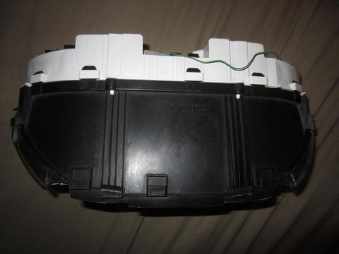
The inside top of the dash bezel also needs shaving down.

The corners need to be notched out around the dash bezel screw mounts. Do this little by little. You want a very tight fit to hold the top in. Do not rush this. It will take quite a bit of time and lot of putting it in and out of the car for test fitting.

The three bottom dash bezel supports also need trimming and shaving. The curved corners of the bottom lip also need removing
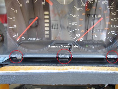

The cluster will need to sit high up to best match the curvature of the dash bezel. The bottom lip of the cluster should sit against the dash bezel.
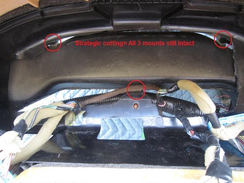
While not necessary to fit the cluster itself, The wires are very tight so I cut the dash behind the cluster a little bit to ease the fit of the connectors/wiring. Notice it is cut strategically to keep the support and strength to the dash. The upper screw mounts and vent mount are still intact.
Wiring
There different ways to accomplish the wiring. My preference on cluster wiring is always to hardwire the new connectors along side with the original connectors. This makes swapping back to stock cluster as simple as plugging it in. It also eliminates the mess and headache of criss crossing wires, then stuffing it behind the cluster with plug in adapter harnesses.
I removed the dash to do the wiring so it would be easier to wire cleanly.

Power and backlighting
There are 4(5 auto) ignition wires on the prelude cluster
A10 wht/yel is dedicated power to immobilizer light and connects to Accord yel fuse 1. Only needed if using immobilizer light.
B9 blk/yel is power for alternator connects to Accord blk/yel
C3 Yel is dedicated power to DRL light. Only needed if using DRL light
C4 Yel is main power for cluster, connects to Accord yel fuse 1.
D9 Yel is power for shift indicators, connects to Accord yel fuse 1.
There are 2(3 auto) black ground wires, A4, B8, D15(auto) all connect to Accord black wire
There are 2(3 auto) red/blk lights on wires, A1, B11, D14(auto) all connect the Accord red/blk lights on
There are 2(3 auto) red dimmer wires, A2, B10, D13(auto) all connect the Accord red dimmer
Gauges
Indicator Lights
Automatic 'S' light and shift indicators
The 90-91 shift position switch outputs ground to illuminate the indicators. The 92-93 Accord and Prelude shift position switch outputs ground to illuminate the indicators except for the D4. The 92-93 Accord and Prelude D4 light is output from the TCU not the shift switch.
Indicator icons
The indicator icons on the prelude are screened on the backside of clear tinted plastic. To change them, I felt it easier to try remove the screening from unwanted areas and put in pieces that already exist.
To remove old icons, they must be wet sanded off with 2000 grit sandpaper. This takes a long time since the plastic needs to remain clear when finished. Chemicals just make a gooey mess and soak through ruining the tinted outer finish. Ask me how I know.

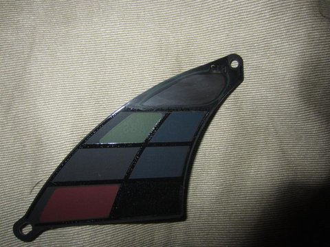

I went to the junkyard and cut a bunch of icons out of clusters. Trim down the new icons to fit the desired location. I used a bit of masking tape to hold it down. The new icons cannot be trimmed enough to fit inside the cluster light boxes so the icon panel sits uneven allowing light to bleed between icons. This requires the cluster to be shaved down until icon panel sits flush. Once flush, you will still get light bleeding between the icons. To resolve this, place some dense memory foam on the edges of the light boxes to seal them.
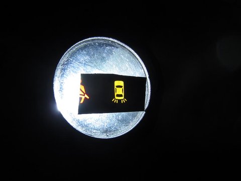

Now you have icons that look oem


The bottom left C756 connector of the accord cluster is different on 89-mid 90 vs late 90-93. 89-mid 90 has a 10 pin connector and the late 90-93 has 7 pin connector. Either version uses the same 7 wires and colors in the same order just different pin locations.


The top c757 connector is also different, 89-early 90 has 16 pins and 92-93 has 18. 89-91 has separate versions for either srs or anti lock each one using the same using indicator location. 92-93 have version have separate indicators locations for abs and srs. The 18 pin is required since a cluster with a full house of indicators needs 17 wires, one more than the 16 pin is capable.


My 90 service manual incorrectly list the terminal numbers in backward order so when comparing with 90 ETM it could cause confusion. Also the ETM has a few mistakes in it. These differences combined with the different connector configurations seem to cause some confusion.
There is also some confusion over Nippon Seiko Vs Nippon Denso clusters. I have found both manufacturers make both connector styles with the exact same wiring. Internally, they are quite different.


Tools Needed
- Philips screwdriver
- Small flat blade
- Crimpers
- Wire strippers
- Drill and drill bits
- 1/4 ratchet with 8mm socket
- Soldering iron
- Dremel with grinding bits
- Pliers
- Cut off wheel
- Airsaw
Materials
- 90-01 Prelude Cluster with connectors and a few extra terminals
- Solder
- Shrink tubing
- 18g or 20g wire
- ABS plastic
- Split loom
- Electrical tape
- Diodes
- 2n2222 transistor
- 10k(I used 8.9k) ohm resistors
- 1k(I used 820) ohm resistor
- razor blade
Cluster Removal
To remove the old cluster is sort of a pain.
Start by removing the console. If you have separate console/ebrake then there are 4 philips screw. If you have attached console/ebrake then there are 6 philips screws. Remove the screws and lift console out of car.
Once center console is out, the radio needs removing. Pull out the ashtray and remove 3 Philips screws holding the carrier. The factory radio is held in with 2 bolts with 8mm heads facing down. Loosen the bolts and slide radio/pocket out to remove.

The dash bezel is held in by 12 screws,
1-behind driver's vent
1-behind coin pocket
1-behind cruise/sunroof switches
1-behind dimmer
2-above cluster
2-behind center vents
2-above radio
2-behind center console

Once the bezel is out remove 4 philips screws holding the cluster in and unplug the 3 connectors. I also removed the steering wheel and lowered the steering column to make things easier but is not required.
Mounting
The Prelude cluster is sized and mounts differently. To support and mount the cluster, make two 'L' shaped abs brackets. These screw into the original cluster mounting spots using a washer on the bottom hole to space out a bit. The top of the cluster will be held in place by the dash bezel.

The Top of the prelude cluster needs to be removed.


The inside top of the dash bezel also needs shaving down.

The corners need to be notched out around the dash bezel screw mounts. Do this little by little. You want a very tight fit to hold the top in. Do not rush this. It will take quite a bit of time and lot of putting it in and out of the car for test fitting.

The three bottom dash bezel supports also need trimming and shaving. The curved corners of the bottom lip also need removing


The cluster will need to sit high up to best match the curvature of the dash bezel. The bottom lip of the cluster should sit against the dash bezel.
While not necessary to fit the cluster itself, The wires are very tight so I cut the dash behind the cluster a little bit to ease the fit of the connectors/wiring. Notice it is cut strategically to keep the support and strength to the dash. The upper screw mounts and vent mount are still intact.

Wiring
There different ways to accomplish the wiring. My preference on cluster wiring is always to hardwire the new connectors along side with the original connectors. This makes swapping back to stock cluster as simple as plugging it in. It also eliminates the mess and headache of criss crossing wires, then stuffing it behind the cluster with plug in adapter harnesses.
I removed the dash to do the wiring so it would be easier to wire cleanly.

Power and backlighting
There are 4(5 auto) ignition wires on the prelude cluster
A10 wht/yel is dedicated power to immobilizer light and connects to Accord yel fuse 1. Only needed if using immobilizer light.
B9 blk/yel is power for alternator connects to Accord blk/yel
C3 Yel is dedicated power to DRL light. Only needed if using DRL light
C4 Yel is main power for cluster, connects to Accord yel fuse 1.
D9 Yel is power for shift indicators, connects to Accord yel fuse 1.
There are 2(3 auto) black ground wires, A4, B8, D15(auto) all connect to Accord black wire
There are 2(3 auto) red/blk lights on wires, A1, B11, D14(auto) all connect the Accord red/blk lights on
There are 2(3 auto) red dimmer wires, A2, B10, D13(auto) all connect the Accord red dimmer
Gauges
- Speedometer: this changes color from Accord's org to Preludes blu/wht.
- Tachometer: this works the same with the same blu color
- Coolant temp: this changes color from Accord's red to Preludes yel/grn.
- Fuel: this changes color from Accord's yel/wht to Preludes yel/blu.
Indicator Lights
- Doors:The Accord has individual door open indicators versus the Prelude's single indicator for both it's doors. The Accord dome light is also output from the cluster after the doors triggers are isolated through diodes then combined. The prelude dome light is combined in the wiring instead of the cluster. The Prelude has two door inputs that are diode isolated. There is also an unused dome light output on the Prelude's circuit board.
If you have a two door accord simply wire the door wires to the Preludes inputs. If you have a 4 door then a little extra work is needed. Since there are already two door inputs, two will have to be added. Luckily there are two open cavities in the same wire connector that have short trace stubs on the circuit board. Diodes are simply soldered to the traces and then together at the existing diodes for the other doors. After that is done add terminals into the empty slots and wire to car's door triggers.

- Driver door:This changes color from Accord's grn/blu to Preludes grn.
- Passenger front door: This changes color from Accord's grn/red to Preludes grn/org.
- Driver rear door:This changes color from Accord's grn/yel to added Prelude terminal pin 4
- Passenger rear door:This changes color from Accord's grn/wht to added Prelude terminal pin 7.
- Dome light:A terminal also needs to be added for the dome light output. This is wired to the car's blk/wht dome light wire. This changes color from Accord's blk/wht to added Prelude terminal pin 13.
- Engine Check:This changes color from Accord's grn/red to Preludes gry/red.
- Trunk open:This works the same with the same color
- Alternator:This works the same with the same color
- Oil:This works the same with the same color
- DRL:This is blacked out and no bulb is installed. The wires are inserted in the connector and applying power and ground will turn on bulb if added.
- SRS:This has a circuit to make it light in case of module failure. The srs module supplies 12v to turn it off. If you don't have srs, applying 12v to the wire will turn it off or the bulb can be removed.
If you have SRS, from reading the electrical drawings I conclude the Accord 91-93 indicator light turns on with ground. The accord might be able to be wired directly if the SRS unit transistor outputs a high 12v when off. When SRS unit transistor is on and low 0v, 12v is removed and indicator lights. Since I don't have SRS, I don't know. If not, the Prelude circuit will need to be bypassed to control the bulb directly.
- High beam:This has two wires controlling it, one for power and one for control
Power changes color from Accord's red/blu to Preludes org/wht.
Control changes color from Accord's red/grn to Preludes red/yel.
- Seat belt light:90-91 this changes color from Accord's yel/red to Preludes red/blu.
92-93 this changes color from Accord's blu/red Preludes red/blu.
- Left turn:This works the same with the same color
- Right turn:This works the same with the same color
- Blank top right:This is blacked out and no bulb is installed. To use, a wire needs to be inserted and bulb installed. Ground to turn on.
- ImmobilizerThis has two wires controlling it. Wht/yel is a dedicated ignition power and blu/blk controls on/off through ground.
- ABS:This has a circuit to make it light in case of module failure. The abs module supplies ground to turn it off. If you don't have ABS, grounding the wire will turn it off or the bulb can be removed.
If you have antilock, from reading the electrical drawings I conclude the Accord 91-93 indicator light turns on with ground. So Prelude circuit will need to be bypassed to control the bulb directly. See photos under brake bulb out.
- Brake Bulb Out Light: The brake bulb out indicator is triggered off/on by a ground through a series of relays in the taillights. The indicator is set to be constantly lit, with a ground used to turn it off.
With the pedal unpressed, the indicator receives the ground through the bulbs filaments. When the brake pedal is pressed, the brake bulbs light eliminating the ground path to the indicator. At the same time, each bulb triggers a relay to supply the ground in series to keep the indicator off. If a bulb is out, it's designated relay will not trigger and the ground path to the bulb is broken causing to the indicator to light.
The prelude does not have a brake bulb out indicator so another light needs to be reassigned. If you dont have ABS you can hook this up to the ABS indicator. If you have ABS or want to make your own icon like I did then reassign it to another bulb. I chose the DRL indicator. Since the ABS has a module that does what we want already and need to be bypassed anyways if used, we can hijack it to control the DRL indicator.
I chose to cut the C2 circuit trace going from the connector to DRL indicator bulb. Then I cut the C6 trace going from the connector to the ABS circuit. Also cut from ABS circuit to the ABS indicator bulb. Solder 3 jumper wires, 1- from DRL input to ABS module input, 2- ABS Input to ABS bulb, 3- ABS module to DRL bulb.
Doing the 3 jumpers gives direct control of the ABS bulb through ground. The DRL bulb now is on all the time and needs ground from tail light circuit to turn off.


- Cruise:This wire changes color from Accord's red to Prelude's blu/blk
- ATTS:This is blacked out on the auto cluster and no bulb is installed. The wire is inserted in the connector and grounding it will turn on bulb if added.
- Brake:Prelude brake light is tied to the alternator light through a diode for some reason. This causes the brake light to stay on. To fix, simply cut one side of the diode and bend it out way.

- Low fuel: this changes color from Accord's grn/red to Preludes lt grn/red.
Automatic 'S' light and shift indicators
The 90-91 shift position switch outputs ground to illuminate the indicators. The 92-93 Accord and Prelude shift position switch outputs ground to illuminate the indicators except for the D4. The 92-93 Accord and Prelude D4 light is output from the TCU not the shift switch.
- P:90-91 this changes color from accord's grn/wht to Preludes blk/blu. 92-93 this changes color from Accord's blu/red Preludes red/blu.
- R: this changes color from Accord's grn/red to Preludes red/blu.
- N: this changes color from Accord's grn to Preludes red
- D4:this changes color from Accord's grn/blk to Preludes blu/red.
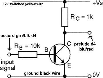
- The Prelude D4 is switched on with 12v instead of ground. When the Accord D4 wire is hooked up the light works opposite of what is required, it turns off when D4 is selected and in any other gear. This can be solved a transistor and few resistors. The transistor will take the 12v input and give a grounded output. The base resistor will have be large otherwise it will be detected as a short and throw a code.
- D3: this changes color from Accord's grn/blu/red to Preludes grn.
- 2: this changes color from Accord's lt grn/wht to Preludes brn
- 1:90-91 this changes color from Accord's yel/red to Preludes red/blu.
- S:The 90-91 accord have a 's' mode switch and 's' light. The 's' mode light is the indicator for TCU error codes. The Prelude does not have a 's' light and uses the D4 light for TCU error codes. The 92-93 do not have an 's' mode or light and uses the D4 light for TCU error codes.
The output from the tcu for the 's' light is 12v. One of the prelude indicators can be reassigned to be the 'S' light. The immobilizer light has its own dedicated power and ground. So instead of wiring the wht/yel to ignition power, wire it to ground.
Take the pink wire and and connect it to grn 's' wire.
I chose to use the atts location and make a 's' indicator. The atts is triggered by ground, so I cut the 12v trace going to the bulb and soldered a jumper to ground.

Indicator icons
The indicator icons on the prelude are screened on the backside of clear tinted plastic. To change them, I felt it easier to try remove the screening from unwanted areas and put in pieces that already exist.
To remove old icons, they must be wet sanded off with 2000 grit sandpaper. This takes a long time since the plastic needs to remain clear when finished. Chemicals just make a gooey mess and soak through ruining the tinted outer finish. Ask me how I know.


I went to the junkyard and cut a bunch of icons out of clusters. Trim down the new icons to fit the desired location. I used a bit of masking tape to hold it down. The new icons cannot be trimmed enough to fit inside the cluster light boxes so the icon panel sits uneven allowing light to bleed between icons. This requires the cluster to be shaved down until icon panel sits flush. Once flush, you will still get light bleeding between the icons. To resolve this, place some dense memory foam on the edges of the light boxes to seal them.


Now you have icons that look oem







Comment