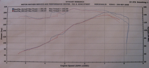
While my tuned (P28) ECU runs my engine well, it doesn't work the dual-runner intake manifold system, which I prefer to keep for drivability reasons, especially in a daily driver.
In this DIY, I am going to go over 2 fairly simple ways I came up with to wire in IAB control without needing an ECU to run it.
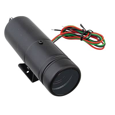
In the first and nicer system I am basically modifying an adjustable shift light and relay to act as an adjustable rpm switch for the IAB solenoid.
This will work for any Honda motor with a dual-runner manifold-F22,H22,H23,B18C,etc.. From what I have found, this is cheaper than buying an rpm activated switch that is fully adjustable, though I don't know why.
The second method will only work for VTEC engine and ECU setups, is not adjustable, and uses only the relay and some wire.
Before I start, I want to go over how the stock system works.
This should help us understand why and how to do this modification.
When the engine is off, the second set of runners is naturally open.
When the engine is on and the rpm is below a set point, the IAB solenoid is energized allowing vacuum from the engine to hold the secondary set of intake runners closed for improved torque and throttle response.
When the higher rpm is reached where more air and shorter runners is desirable, the IAB solenoid should be electrically switched off, allowing the intake to return to it's naturally open state.
The stock signal to open is around 4800rpm, and you definitely won't want to be in VTEC with them closed.
With the following system, you can put the switchover at any rpm you like.
METHOD ONE- Fully Adjustable Standalone IAB Control:
*adj. knob pic

Basic wiring skills are required.
If you know how to splice, strip and solder, you'll be fine.
Parts Needed:
adjustable rpm shift light <$36
I got mine from Summit Racing, Part #SUM-G2945.
But any light that is adjustable and has a 12V (NON-LED) bulb should work.

One 12volt SPDT Relay (20/30+amp recommended) <$5
These are standard Single Pole Double Throw Relays.
They have 5 pins, and should come with a connector and some wire.
Mine are by Bosch from eBay, Radio Shack and maybe some automotive stores should have them.
FYI, here is a link to a short description of how this relay works
http://www.the12volt.com/relays/relays.asp
*relay pic and overview

Tools Needed:
Multitester
soldering iron & solder
heat shrink tubing
lighter/heat gun
wire cutter/strippers
small phillips screwdriver
*Tools pic

Not Pictured:
wire
ring terminal(s) for ground wire, 1/4"hole 14-16ga.
10 mm wrench or ratchet & socket for ground bolts
Optional:
wire loom
indicator light
Preparing:
Decide whether you want to mount the shift light under the hood or inside the car.
I have had mine mounted inside, but didn't change the adjustment much once set.
I decided to put it under the hood on my CB, it makes the wiring easier, but you have to find a good spot to mount it.
You'll notice mine is crushed a bit since it didn't (used to) fit under the hood where I put it.
If you decide to install everything in the car, you will need to run a few wires through the firewall, and may want to splice into the ECU wires for power(pin A25) and ground(pin A23).
The pics in this DIY are from my underhood install, but I will provide info for both locations.
*installed in bay pic

1. Modifying the shift light.
a) Use the screwdriver to remove the screws holding the front housing of the shift light, then remove the housing to gain access to the bulb.
b) Remove the bulb and solder two wires to the bulb contacts. Make the wires long enough to reach the relay when installed. Scratching or sanding the contacts a bit should help the solder stick if needed.
I checked polarity and ran the positive side of the bulb (gray wire in pic) to 86 on the relay, but I don't think polarity actually matters here.
c) Modify the front shift light housing (to not cut the wires) and reinstall, or cover the end of the main housing with a rubber cap, electrical tape, etc.
d) Follow the instructions for the light, make sure it is configured for the right # of cylinders!
*shiftlight mod pic

2. Locating power and tach signals.
Power must be supplied to the relay and shift light, which also requires a tach signal.
I suggest splicing into the right engine bay wiring harness.
Get out the multitester and use the pic below to identify the stock wires.
Check for voltage on the car-side connector pin to ground with the key on.
Check to confirm the tach signal wire by pulling both pictured connectors and checking continuity between ends.
Later, when you go to splice into the wires, do so behind these connectors.
This way you can avoid having to cut wires if the engine ever needs to be removed.
The connectors must be removed from the brackets before they can be separated.
*wiring check pic

3. Wiring and installation.
Disconnect the negative battery terminal and any active capacitors, etc., blah blah. Cut the power.
Mount the shift light and relay in the engine bay, don't let them get crushed by the hood like mine.
Wiring Time!
Power gets spliced from the black/yellow engine bay wire and fed to both the shift light, and terminal 30 on the relay.
The shift light ground wire should get a ring terminal and go on a ground bolt.
The blue wire with the tach signal gets spliced to the shiftlight.
The two wires from the bulb contacts of the light go to the coil circuit of the relay, 86 and 85.
Terminal 87 (switched on) of the relay will not be used with the shift light unless you want to use it for an indicator light showing intake release.
Terminal 87a (normally on) is wired to the clip-side terminal of the IAB solenoid connector/plug.
If you have stock IAB wiring, you will need to cut the black/yellow wire on the plug, tape off the harness side (or use for power), and wire into the plug side.
The non clip-side terminal of the IAB plug should get a ring terminal and go to a ground bolt, but will work on most bolts of the intake manifold or engine.
If you have stock IAB wiring, you can locate the pink/blue wire in the above pic and ground the wire anywhere before the ECU.
*photowiring diagram

*ground locations pic

4. Install test.
a) Double-check your wiring, plug in all connectors, insulate all bare wire, and hook the battery up.
b) With the car still off, look at the position of the iab rotor on the driver side of the intake manifold.
c) Turn the car on, let it idle, get out and check to see that the iab rotor has moved to close the runners.
Another way to check at idle is to temporarily disconnect the hose running to the iab diaphragm towards the top of the intake manifold, and see if it moves the IAB mechanism.
A friend could hear the relay click when the key is first turned to ON, engine off, if it is working correctly.
d) Once the engine has warmed up a bit, the switching function can be tested.
Set the shift light's rpm adjustment somewhere on the low side.
Have a friend hit the gas or use the throttle rotor to raise the engine rpm until you see the rotor and mechanism move on the left side of the intake manifold.
5. Finishing up.
If everything looks good, turn the car off, solder and heatshrink all connections, or use electrical tape if you have to.
Insulate all bare wire and install wire loom if desired.
6. Set the dial where you want the IABs to open.
Go drive your car and laugh in the face of compromise!
IN-CAR INSTALL variations:
a) You can wire into the main relay's key-on power and ground at the ECU wiring harness.
The black wire at pin A23 is ground.
The black/yellow wire at pin A25 is power.
b) If you have stock IAB wiring, you can cut the pink/blue ECU wire at A17, and hook relay pin 87a to the outgoing end..
Then go under the hood.
Cut off the stock solenoid plug and solder the pink/blue harness wire's end to the black/yellow connector side wire.
Ground the pink/blue wire coming out from the connector.
Tape off the black/yellow wire from the harness.
Find or run the tach signal inside (Isn't it at the ECU somewhere too?)
So now when the ignition comes on and there is engine vacuum, the relay-powered solenoid holds the runners closed..
Until the selected rpm is reached, then the shift "light" switches the relay and power to the solenoid is cut. Just like stock.
In this DIY, I am going to go over 2 fairly simple ways I came up with to wire in IAB control without needing an ECU to run it.
In the first and nicer system I am basically modifying an adjustable shift light and relay to act as an adjustable rpm switch for the IAB solenoid.
This will work for any Honda motor with a dual-runner manifold-F22,H22,H23,B18C,etc.. From what I have found, this is cheaper than buying an rpm activated switch that is fully adjustable, though I don't know why.
The second method will only work for VTEC engine and ECU setups, is not adjustable, and uses only the relay and some wire.
Before I start, I want to go over how the stock system works.
This should help us understand why and how to do this modification.
When the engine is off, the second set of runners is naturally open.
When the engine is on and the rpm is below a set point, the IAB solenoid is energized allowing vacuum from the engine to hold the secondary set of intake runners closed for improved torque and throttle response.
When the higher rpm is reached where more air and shorter runners is desirable, the IAB solenoid should be electrically switched off, allowing the intake to return to it's naturally open state.
The stock signal to open is around 4800rpm, and you definitely won't want to be in VTEC with them closed.
With the following system, you can put the switchover at any rpm you like.
METHOD ONE- Fully Adjustable Standalone IAB Control:
*adj. knob pic

Basic wiring skills are required.
If you know how to splice, strip and solder, you'll be fine.
Parts Needed:
adjustable rpm shift light <$36
I got mine from Summit Racing, Part #SUM-G2945.
But any light that is adjustable and has a 12V (NON-LED) bulb should work.

One 12volt SPDT Relay (20/30+amp recommended) <$5
These are standard Single Pole Double Throw Relays.
They have 5 pins, and should come with a connector and some wire.
Mine are by Bosch from eBay, Radio Shack and maybe some automotive stores should have them.
FYI, here is a link to a short description of how this relay works
http://www.the12volt.com/relays/relays.asp
*relay pic and overview

Tools Needed:
Multitester
soldering iron & solder
heat shrink tubing
lighter/heat gun
wire cutter/strippers
small phillips screwdriver
*Tools pic

Not Pictured:
wire
ring terminal(s) for ground wire, 1/4"hole 14-16ga.
10 mm wrench or ratchet & socket for ground bolts
Optional:
wire loom
indicator light
Preparing:
Decide whether you want to mount the shift light under the hood or inside the car.
I have had mine mounted inside, but didn't change the adjustment much once set.
I decided to put it under the hood on my CB, it makes the wiring easier, but you have to find a good spot to mount it.
You'll notice mine is crushed a bit since it didn't (used to) fit under the hood where I put it.
If you decide to install everything in the car, you will need to run a few wires through the firewall, and may want to splice into the ECU wires for power(pin A25) and ground(pin A23).
The pics in this DIY are from my underhood install, but I will provide info for both locations.
*installed in bay pic

1. Modifying the shift light.
a) Use the screwdriver to remove the screws holding the front housing of the shift light, then remove the housing to gain access to the bulb.
b) Remove the bulb and solder two wires to the bulb contacts. Make the wires long enough to reach the relay when installed. Scratching or sanding the contacts a bit should help the solder stick if needed.
I checked polarity and ran the positive side of the bulb (gray wire in pic) to 86 on the relay, but I don't think polarity actually matters here.
c) Modify the front shift light housing (to not cut the wires) and reinstall, or cover the end of the main housing with a rubber cap, electrical tape, etc.
d) Follow the instructions for the light, make sure it is configured for the right # of cylinders!
*shiftlight mod pic

2. Locating power and tach signals.
Power must be supplied to the relay and shift light, which also requires a tach signal.
I suggest splicing into the right engine bay wiring harness.
Get out the multitester and use the pic below to identify the stock wires.
Check for voltage on the car-side connector pin to ground with the key on.
Check to confirm the tach signal wire by pulling both pictured connectors and checking continuity between ends.
Later, when you go to splice into the wires, do so behind these connectors.
This way you can avoid having to cut wires if the engine ever needs to be removed.
The connectors must be removed from the brackets before they can be separated.
*wiring check pic

3. Wiring and installation.
Disconnect the negative battery terminal and any active capacitors, etc., blah blah. Cut the power.
Mount the shift light and relay in the engine bay, don't let them get crushed by the hood like mine.
Wiring Time!
Power gets spliced from the black/yellow engine bay wire and fed to both the shift light, and terminal 30 on the relay.
The shift light ground wire should get a ring terminal and go on a ground bolt.
The blue wire with the tach signal gets spliced to the shiftlight.
The two wires from the bulb contacts of the light go to the coil circuit of the relay, 86 and 85.
Terminal 87 (switched on) of the relay will not be used with the shift light unless you want to use it for an indicator light showing intake release.
Terminal 87a (normally on) is wired to the clip-side terminal of the IAB solenoid connector/plug.
If you have stock IAB wiring, you will need to cut the black/yellow wire on the plug, tape off the harness side (or use for power), and wire into the plug side.
The non clip-side terminal of the IAB plug should get a ring terminal and go to a ground bolt, but will work on most bolts of the intake manifold or engine.
If you have stock IAB wiring, you can locate the pink/blue wire in the above pic and ground the wire anywhere before the ECU.
*photowiring diagram

*ground locations pic

4. Install test.
a) Double-check your wiring, plug in all connectors, insulate all bare wire, and hook the battery up.
b) With the car still off, look at the position of the iab rotor on the driver side of the intake manifold.
c) Turn the car on, let it idle, get out and check to see that the iab rotor has moved to close the runners.
Another way to check at idle is to temporarily disconnect the hose running to the iab diaphragm towards the top of the intake manifold, and see if it moves the IAB mechanism.
A friend could hear the relay click when the key is first turned to ON, engine off, if it is working correctly.
d) Once the engine has warmed up a bit, the switching function can be tested.
Set the shift light's rpm adjustment somewhere on the low side.
Have a friend hit the gas or use the throttle rotor to raise the engine rpm until you see the rotor and mechanism move on the left side of the intake manifold.
5. Finishing up.
If everything looks good, turn the car off, solder and heatshrink all connections, or use electrical tape if you have to.
Insulate all bare wire and install wire loom if desired.
6. Set the dial where you want the IABs to open.
Go drive your car and laugh in the face of compromise!
IN-CAR INSTALL variations:
a) You can wire into the main relay's key-on power and ground at the ECU wiring harness.
The black wire at pin A23 is ground.
The black/yellow wire at pin A25 is power.
b) If you have stock IAB wiring, you can cut the pink/blue ECU wire at A17, and hook relay pin 87a to the outgoing end..
Then go under the hood.
Cut off the stock solenoid plug and solder the pink/blue harness wire's end to the black/yellow connector side wire.
Ground the pink/blue wire coming out from the connector.
Tape off the black/yellow wire from the harness.
Find or run the tach signal inside (Isn't it at the ECU somewhere too?)
So now when the ignition comes on and there is engine vacuum, the relay-powered solenoid holds the runners closed..
Until the selected rpm is reached, then the shift "light" switches the relay and power to the solenoid is cut. Just like stock.


 New & Improved 93 Accord EX Coupe


 __
__
Comment