This is one of those where there is a little info out there but mostly incomplete. With all the threads I searched, I only found one claiming that it was fully installed. Even then there are only pictures of the control unit and none of the other required parts. I debated whether or not to even bother with a write up but ultimately against my better judgement I did it anyways.
This write up explains most everything in detail but don't go riding off on your unicorns to mystic lands just yet. This a fairly involved process that is time consuming. Expect to give yourself 3-4 days to complete this cleanly. It could be done in a weekend if you want to do a hack job. For complete operation the dash has to come in order to remove the heater unit. While installing the dcc is not overly difficult, it is very involved and beyond the capabilities of the inexperienced. Meaning if you don't understand it, you probably don't have skills required to complete this.
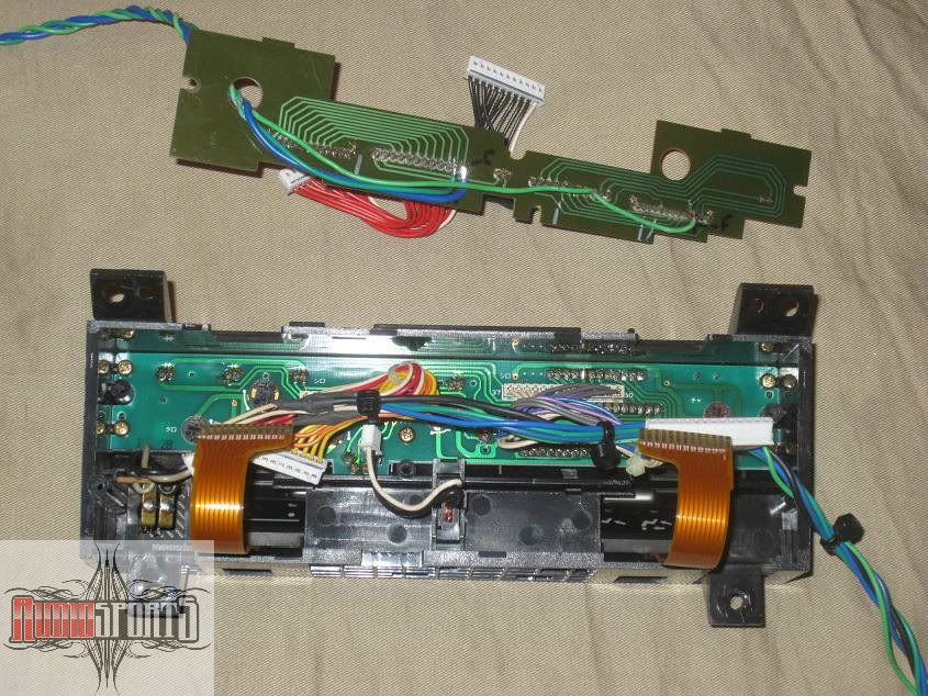
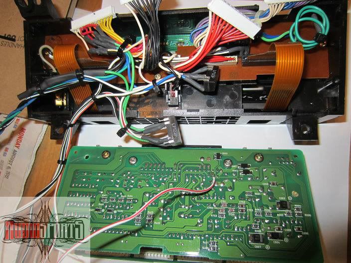
The 4th gen Accord digital climate control system differs from the USDM system by a few things. Luckily all you need from jdmland is the the controller as the rest of the parts can be sourced from a variety of US cars. As far as wiring goes, there wasn't a cb7 specific diagram that I could find. After about 15 hrs comparing diagrams from various Honda's, I figured 95% of it. The rest was simply tested with a vom and by process of elimination.
parts I used
Wiring diagram I created
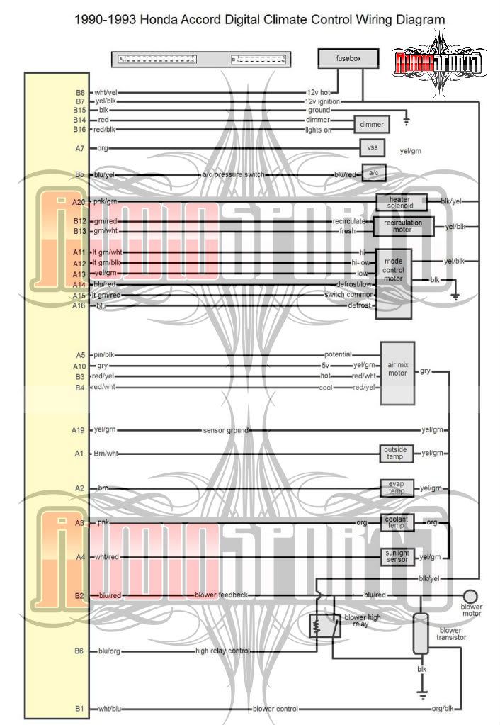
Wiring connector pin out
Since I was unsure of how everything would work out, I started out to get the basics that just required simple wiring working before removing the dash.
Remove the console and dash bezel to get to the heater control out. I wanted to make a plug so I didn't have to cut the connectors off harness. I cut female side of an icu then soldered the dcc wires to it. Then I depinned the terminals of the stock male connector and inserted them into the ICU connector.
Basic Power Wiring
the basic power wiring is all present except for 12v constant power which can spliced into at the hazard switch above.
Wire in the 12v, ign, gnd, a/c signal, illumnation and dimmer.
dcc 12v wht/yel to hazard wht/grn
dcc ign yel/blk to heater blk/yel
dcc gnd blk to heater blk
dcc a/c blu/yel to heater blu/red
dcc ill red/blk to heater red/blk
dcc dim red to heater red
Test it out make sure it powers up, the backlighting works, and the compressor engages. Next wire the mode control motor and the recirculation motor. These are color to color with existing accord wires.
Fresh/Recirc and Mode Wiring
dcc grn/red to heater grn/red fresh
dcc grn/wht to heater grn/wht recirculate
dcc lt/grn/wht to heater lt/grn wht mode high
dcc lt grn/blk to heater lt grn/blk mode hi/low
dcc lt yel/grn to heater yel/grn modelow
dcc blu/red to heater blu/red mode defrost/low
dcc lt grn/red to lt grn/red mode common
dcc blu to heater blu mode defrost
After wiring, reconnect the original blower switch and turn on to get some air moving, test mode motor to make sure all is working. Test the fresh/recirculation motor. If all is well, move on to the blower transistor and high relay.
Blower Transistor
Remove the glove box, glove box bracket, and bolts holding right side of dash. Unbolt the ecu/tcu bracket and swing out of way. Remove two screws from bottom of blower to remove bottom lower trim. Remove clip to remove blower lower section. Remove the the 3 nuts and and unplug the wiring connectors then carefully remove blower motor.
In order to wire the blower motor to the dcc, you need to replace the stock blower resistor with a transistor. The jdm cb7 mounts the transistor to the evaporator case. While this an optimum spot due to airflow, the USDM car evaporator does not have a spot where the transistor can mount so I just mounted it to where the resistor goes. You will also need to add a bypass relay to bypass the transisitor for when full output is selected. Any standard relay will work but I kept it factory and used a stock relay from a 1st gen Acura CL. Cut off the existing wires at the resistor and wire as shown below. This eliminates the need to run wires to the control unit and blower will unplug like normal.
At transistor connector wiring
blu/red transistor blower output blu/red blower reisitor connector
org/blk transistor control blu/wht blower resistor connector
blk transitor ground blu/blk blower resistor connector
at high relay wiring
blk/yel relay power blu blower resistor connector
blu/org relay control blu/yel blower resistor connector
blu/red relay output blu/red blower resistor connector
blk relay input blu/blk blower resistor connector
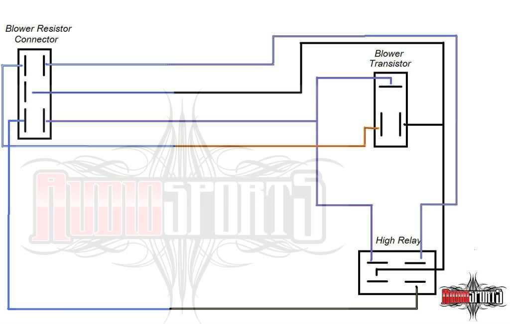
Blower transistor wiring
After completing the wiring at the blower rewire the heater control blower speed connector as below.
At heater panel wiring
blu/red feedback blu/red at blower switch connecter
blu/org hi relay blu/yel at blower switch connector
wht/blu transistor control blu/wht at blower switch connector
yel/blk relay power blu at blower switch connector
At blower switch connector
blk ground blu/blk at blower switch connector
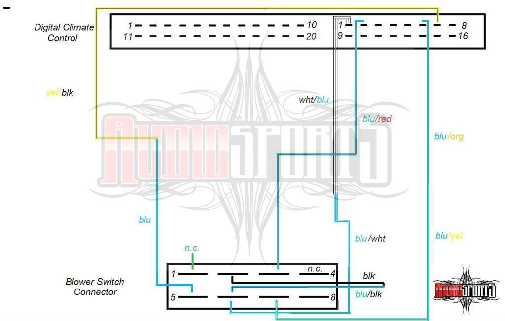
Blower switch wiring diagram
The jdm dcc uses a transistor that looks similar to the g2 legend but that will not fit into the accord blower housing. The first gen legend does not fit and the 1st gen tl is not accessible enough to even try. The first gen CL transistor also does not fit but it can be modified to fit. The CL transistor and accord resistor mount differently. I cut down the larger transistor mounting base on a belt sander until it fit the opening. To install in the blower, I simply sandwiched the blower housing between the transistor heat sink and mounting base. I added a drop of thread locker just to be safe since removing the blower is a pain. I also bolted up the high speed bypass relay to the back of the blower.
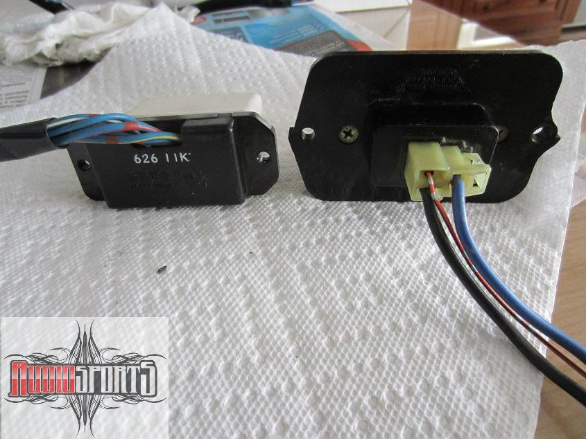
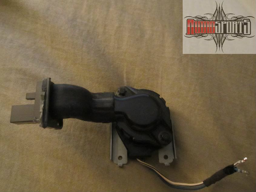
Comparison, accord resistor on left, CL transistor on right
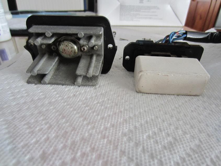
Comparison, CL transistor on left, accord resistor on right
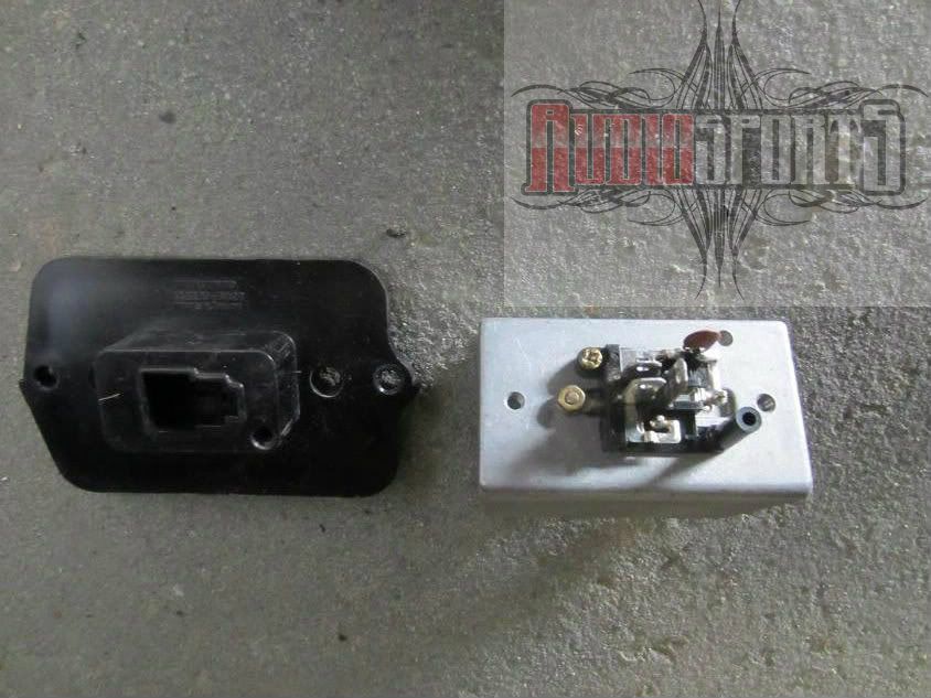
CL transistor separated
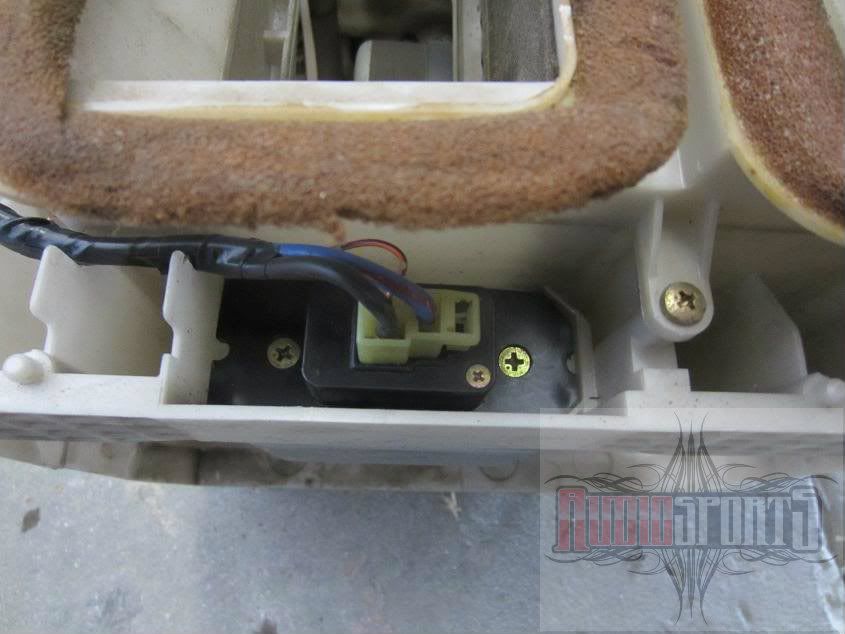
CL transistor base plate ground down to fit blower housing
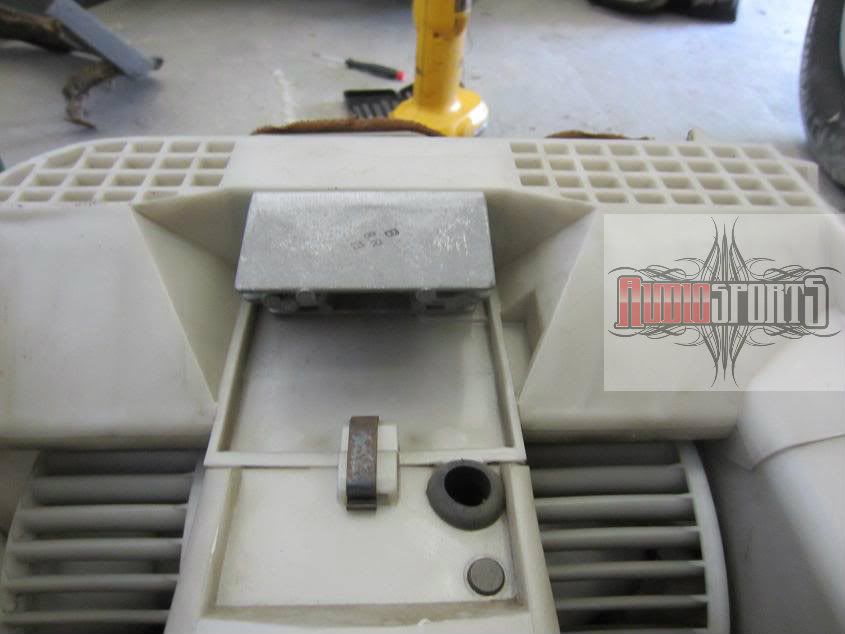
Transistor heat sink in blower housing
Air mix motor
One the biggest hurdles to installing the digital climate control system is that the air mix on the standard accord controller is controlled by a cable. The DCC system use a motor to control the air mix. Since the all the cb7 DCC I have seen comes from RHD cars, none of the stock motor/linkage stuff bolts on the LHD heater box.
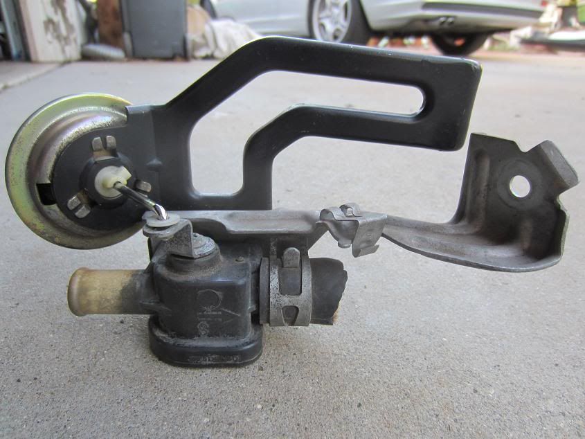
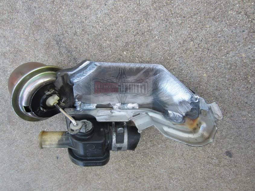
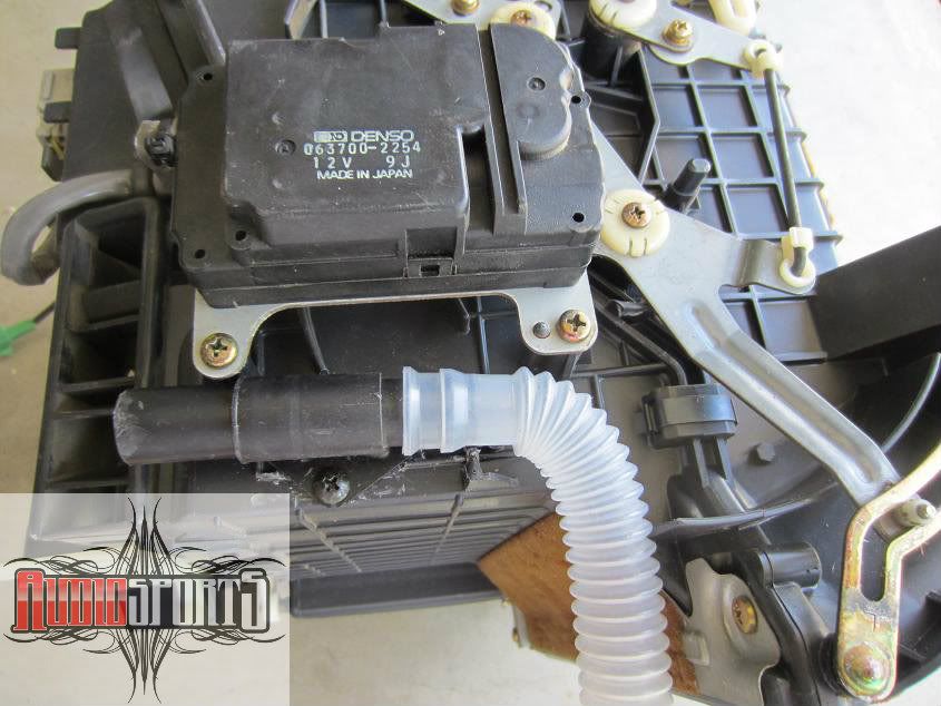
I used an air mix motor from a 1st gen Acura CL. To mount close to factory jdm spot, all linkages need to be redone or modified plus a new pivot arm made. To make the install simpler, the motor can to be mounted so the output gear is directly centered over the air mix linkage center pivot. This is so it will have the same arc on the motor control arm as the air mix linkage arm. The location the motor needs to be mounted in, is where the floor vent outlet clips on the bottom of the heater housing.
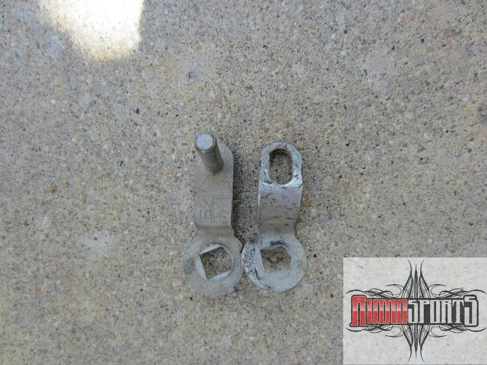
I made a bracket to bolt to the motor and to the bottom heater outlet. On the other side of the motor, I made a bracket from the motor to the metal 'L' tab that is used to clip the floor outlet vent on. I then had the three pieces welded together. Once the motor is perfectly centered, set the motor and air mix linkage to full hot. Loosen the motor arm's nut and align the arm with the air mix linkage control arm pin. Mark the motor's arm where a hole will need to be for the linkage arm pin. Drill a hole and slot it slightly so there will be no chance of binding. Use the plastic insulator so it moves freely.
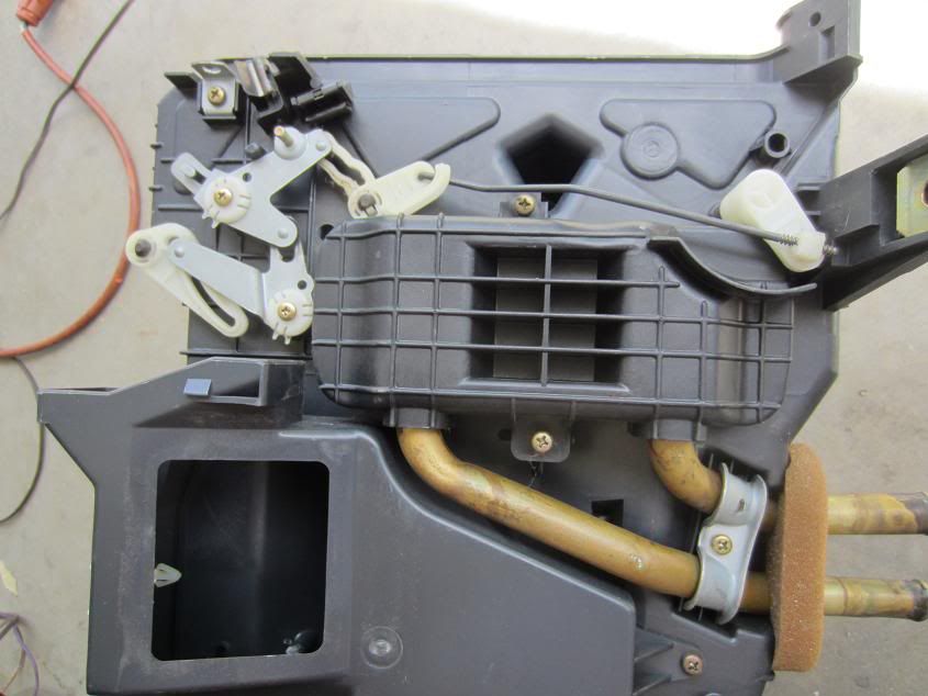
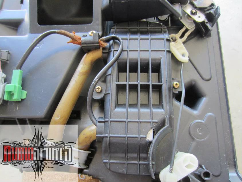
Heater box before
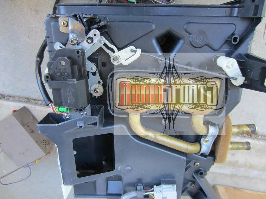
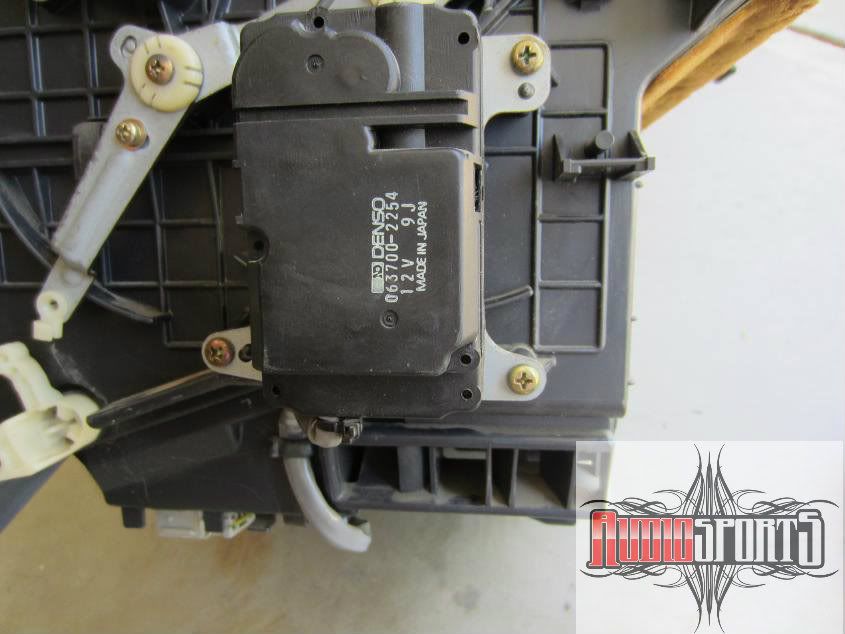
Air mix motor and custom bracket
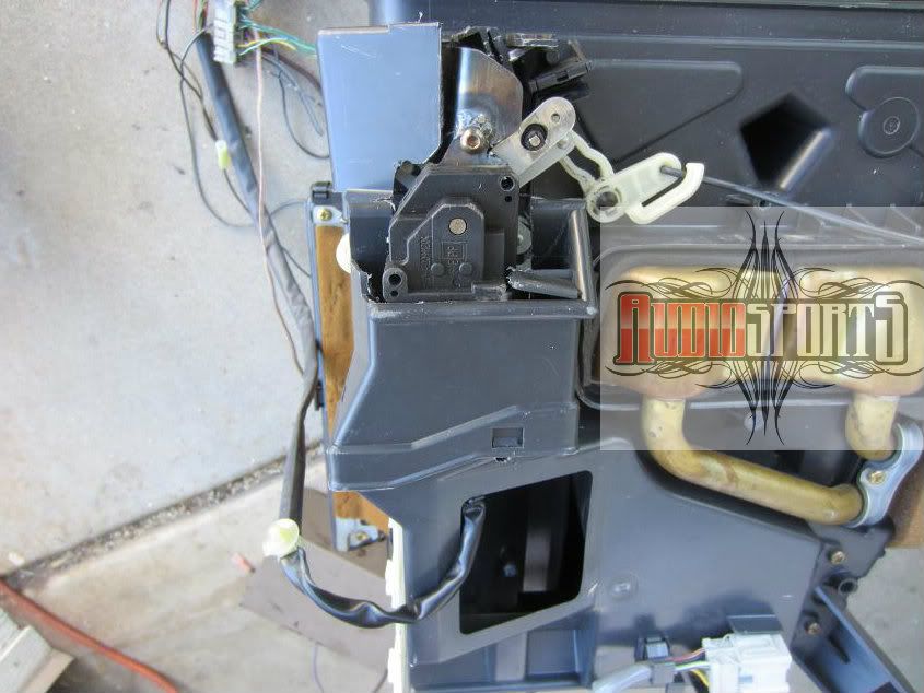
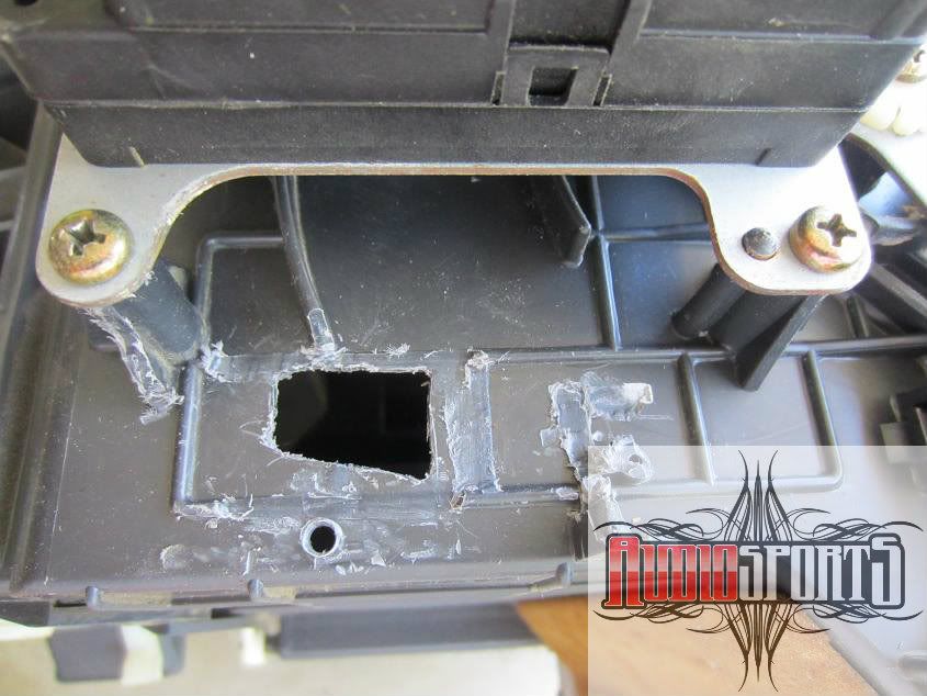
Air mix installed with vent outlet cut out
In action
The air mix motor actually rotates the wrong direction. Hot is cool and cool is hot. The motor operates on reverse polarity output from the dcc so this easily fixed by swapping the two control wires. Now the hot/cool will be in sync but will go to full cool or full hot with nothing in between. What makes it operate in steps is feed back from a potentiometer in the air mix motor. The feed back is backwards when the motor wires are swapped for hot/cool direction. This is also fixed simply by swapping the 5v reference and sensor ground wires going into the pot.
wiring
pnk/blk to dcc pnk/blk
gry to dcc grn/yel
grn/yel to dcc gry
red/wht to dcc red/yel
red/yel to dcc red/wht
This write up explains most everything in detail but don't go riding off on your unicorns to mystic lands just yet. This a fairly involved process that is time consuming. Expect to give yourself 3-4 days to complete this cleanly. It could be done in a weekend if you want to do a hack job. For complete operation the dash has to come in order to remove the heater unit. While installing the dcc is not overly difficult, it is very involved and beyond the capabilities of the inexperienced. Meaning if you don't understand it, you probably don't have skills required to complete this.
The 4th gen Accord digital climate control system differs from the USDM system by a few things. Luckily all you need from jdmland is the the controller as the rest of the parts can be sourced from a variety of US cars. As far as wiring goes, there wasn't a cb7 specific diagram that I could find. After about 15 hrs comparing diagrams from various Honda's, I figured 95% of it. The rest was simply tested with a vom and by process of elimination.
parts I used
- Honda 4th gen Accord Digital Climate Control
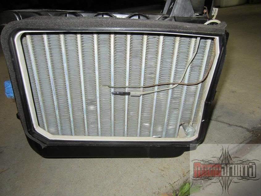
Honda 4th gen Accord Evaporator temp switch grommet
Acura 1st gen Cl blower transistor
Acura 1st gen Cl hi speed fan relay
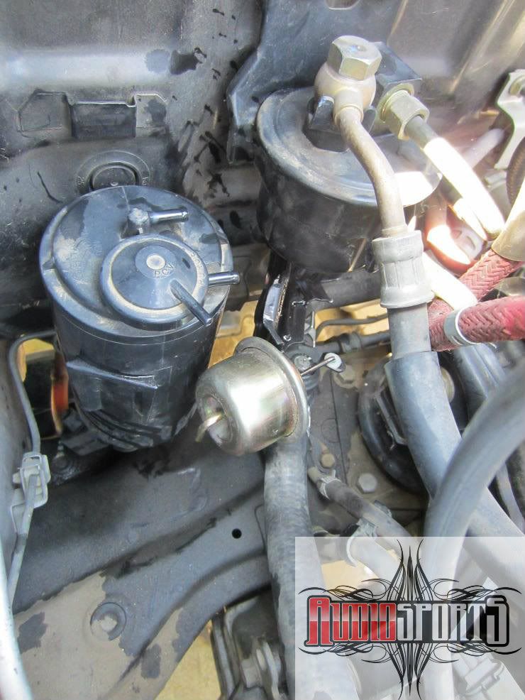
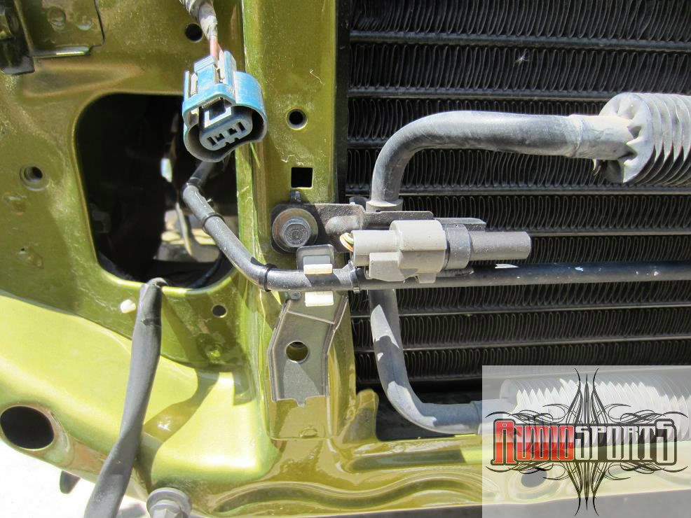
Acura 1st gen Cl Outside air temp sensor
Acura 1st gen Cl sunlight sensor
Acura 1st gen Cl air mix motor
Acura 1st gen Cl evap temperature sensor
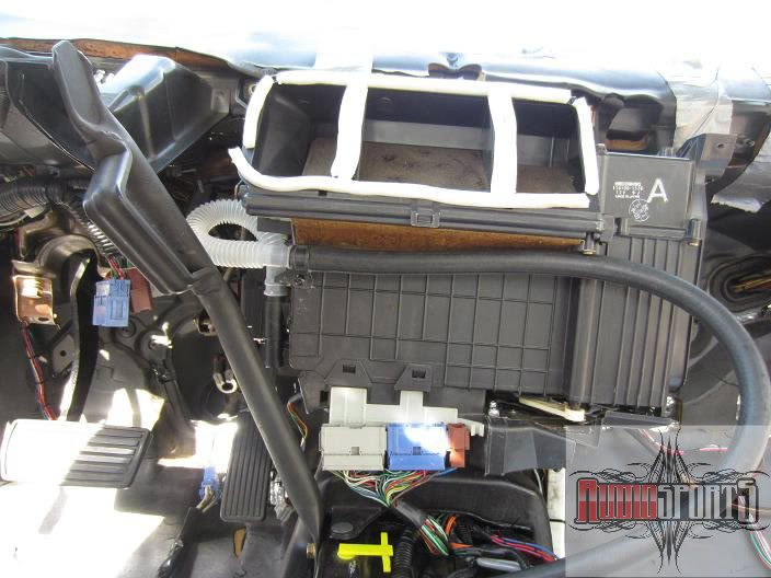
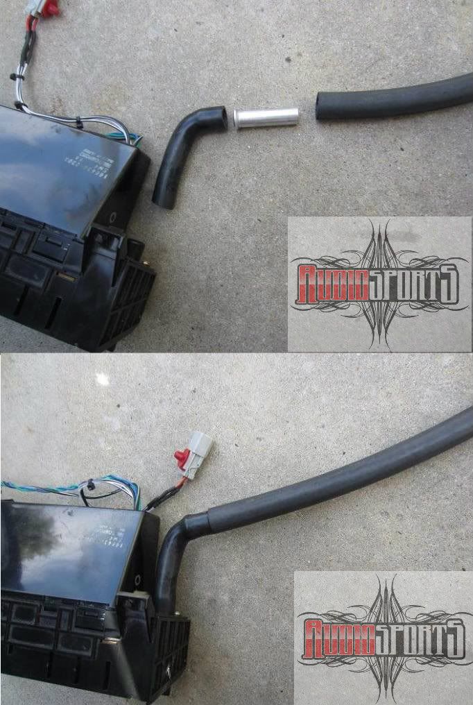
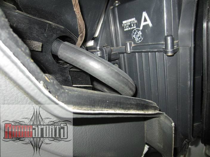
Acura 1st gen Cl aspirator union and rubber hose
Acura 2nd gen TL aspirator and plastic hose
Acura 1st gen Legend coolant temperature sensor
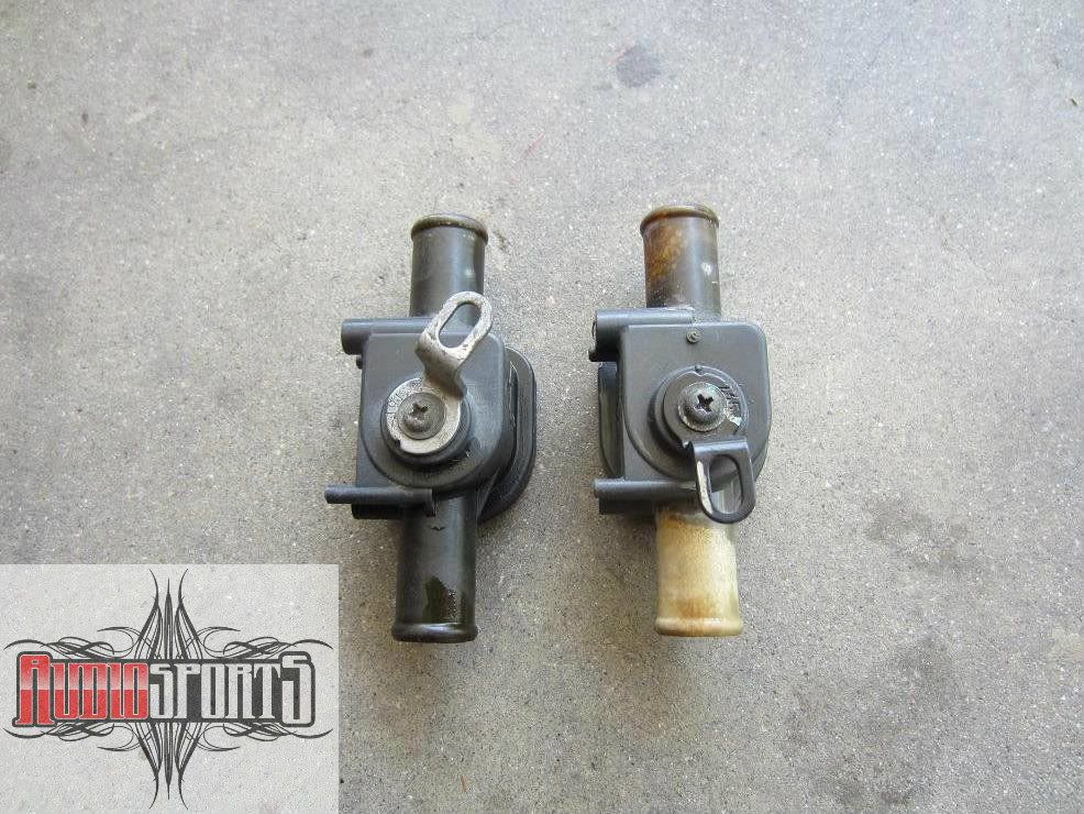
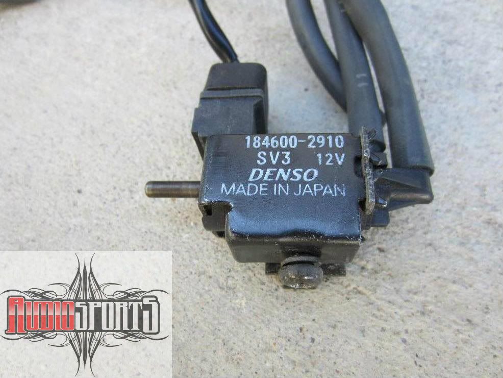
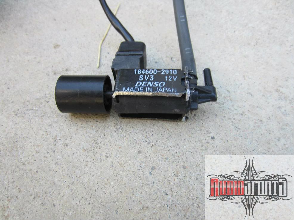
Acura 1st gen TL heater valve and solenoid
Wiring diagram I created

Wiring connector pin out
Since I was unsure of how everything would work out, I started out to get the basics that just required simple wiring working before removing the dash.
Remove the console and dash bezel to get to the heater control out. I wanted to make a plug so I didn't have to cut the connectors off harness. I cut female side of an icu then soldered the dcc wires to it. Then I depinned the terminals of the stock male connector and inserted them into the ICU connector.
Basic Power Wiring
the basic power wiring is all present except for 12v constant power which can spliced into at the hazard switch above.
Wire in the 12v, ign, gnd, a/c signal, illumnation and dimmer.
dcc 12v wht/yel to hazard wht/grn
dcc ign yel/blk to heater blk/yel
dcc gnd blk to heater blk
dcc a/c blu/yel to heater blu/red
dcc ill red/blk to heater red/blk
dcc dim red to heater red
Test it out make sure it powers up, the backlighting works, and the compressor engages. Next wire the mode control motor and the recirculation motor. These are color to color with existing accord wires.
Fresh/Recirc and Mode Wiring
dcc grn/red to heater grn/red fresh
dcc grn/wht to heater grn/wht recirculate
dcc lt/grn/wht to heater lt/grn wht mode high
dcc lt grn/blk to heater lt grn/blk mode hi/low
dcc lt yel/grn to heater yel/grn modelow
dcc blu/red to heater blu/red mode defrost/low
dcc lt grn/red to lt grn/red mode common
dcc blu to heater blu mode defrost
After wiring, reconnect the original blower switch and turn on to get some air moving, test mode motor to make sure all is working. Test the fresh/recirculation motor. If all is well, move on to the blower transistor and high relay.
Blower Transistor
Remove the glove box, glove box bracket, and bolts holding right side of dash. Unbolt the ecu/tcu bracket and swing out of way. Remove two screws from bottom of blower to remove bottom lower trim. Remove clip to remove blower lower section. Remove the the 3 nuts and and unplug the wiring connectors then carefully remove blower motor.
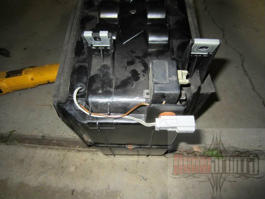
In order to wire the blower motor to the dcc, you need to replace the stock blower resistor with a transistor. The jdm cb7 mounts the transistor to the evaporator case. While this an optimum spot due to airflow, the USDM car evaporator does not have a spot where the transistor can mount so I just mounted it to where the resistor goes. You will also need to add a bypass relay to bypass the transisitor for when full output is selected. Any standard relay will work but I kept it factory and used a stock relay from a 1st gen Acura CL. Cut off the existing wires at the resistor and wire as shown below. This eliminates the need to run wires to the control unit and blower will unplug like normal.
At transistor connector wiring
blu/red transistor blower output blu/red blower reisitor connector
org/blk transistor control blu/wht blower resistor connector
blk transitor ground blu/blk blower resistor connector
at high relay wiring
blk/yel relay power blu blower resistor connector
blu/org relay control blu/yel blower resistor connector
blu/red relay output blu/red blower resistor connector
blk relay input blu/blk blower resistor connector

Blower transistor wiring
After completing the wiring at the blower rewire the heater control blower speed connector as below.
At heater panel wiring
blu/red feedback blu/red at blower switch connecter
blu/org hi relay blu/yel at blower switch connector
wht/blu transistor control blu/wht at blower switch connector
yel/blk relay power blu at blower switch connector
At blower switch connector
blk ground blu/blk at blower switch connector

Blower switch wiring diagram
The jdm dcc uses a transistor that looks similar to the g2 legend but that will not fit into the accord blower housing. The first gen legend does not fit and the 1st gen tl is not accessible enough to even try. The first gen CL transistor also does not fit but it can be modified to fit. The CL transistor and accord resistor mount differently. I cut down the larger transistor mounting base on a belt sander until it fit the opening. To install in the blower, I simply sandwiched the blower housing between the transistor heat sink and mounting base. I added a drop of thread locker just to be safe since removing the blower is a pain. I also bolted up the high speed bypass relay to the back of the blower.

Comparison, accord resistor on left, CL transistor on right

Comparison, CL transistor on left, accord resistor on right

CL transistor separated

CL transistor base plate ground down to fit blower housing

Transistor heat sink in blower housing
Air mix motor
One the biggest hurdles to installing the digital climate control system is that the air mix on the standard accord controller is controlled by a cable. The DCC system use a motor to control the air mix. Since the all the cb7 DCC I have seen comes from RHD cars, none of the stock motor/linkage stuff bolts on the LHD heater box.
I used an air mix motor from a 1st gen Acura CL. To mount close to factory jdm spot, all linkages need to be redone or modified plus a new pivot arm made. To make the install simpler, the motor can to be mounted so the output gear is directly centered over the air mix linkage center pivot. This is so it will have the same arc on the motor control arm as the air mix linkage arm. The location the motor needs to be mounted in, is where the floor vent outlet clips on the bottom of the heater housing.
I made a bracket to bolt to the motor and to the bottom heater outlet. On the other side of the motor, I made a bracket from the motor to the metal 'L' tab that is used to clip the floor outlet vent on. I then had the three pieces welded together. Once the motor is perfectly centered, set the motor and air mix linkage to full hot. Loosen the motor arm's nut and align the arm with the air mix linkage control arm pin. Mark the motor's arm where a hole will need to be for the linkage arm pin. Drill a hole and slot it slightly so there will be no chance of binding. Use the plastic insulator so it moves freely.

Heater box before

Air mix motor and custom bracket

Air mix installed with vent outlet cut out
In action
The air mix motor actually rotates the wrong direction. Hot is cool and cool is hot. The motor operates on reverse polarity output from the dcc so this easily fixed by swapping the two control wires. Now the hot/cool will be in sync but will go to full cool or full hot with nothing in between. What makes it operate in steps is feed back from a potentiometer in the air mix motor. The feed back is backwards when the motor wires are swapped for hot/cool direction. This is also fixed simply by swapping the 5v reference and sensor ground wires going into the pot.
wiring
pnk/blk to dcc pnk/blk
gry to dcc grn/yel
grn/yel to dcc gry
red/wht to dcc red/yel
red/yel to dcc red/wht





Comment