Announcement

Collapse
No announcement yet.

Cluster adjustment screws.....

Collapse
X
 
  • Filter
  • Time
  • Show
Clear All
new posts

    Cluster adjustment screws.....

    there was another thread on this already but no solid answers were ever given as to the proper adjustment for these screws:


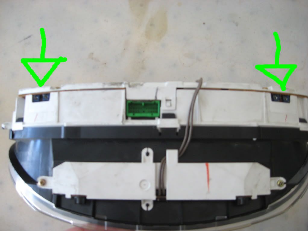
    the reason i bring this up is that i just got a pair of clusters that have the tape that covers these adjusters removed.

    i dont know for certain if they have been messed with. or for that matter what theyre function is.

    but just in case i would like to set them to factory specs for when i swap it into my car.

    my car is a 92 LX with a h22a and mp1a trans if it makes a difference.

    any input is most welcome.

    thanks tuners

    Bought from: Bisimoto, FuncOvrForm, HondaGuy1212, wed3k, Konigstiger, 1st2run, BillKisme, k-mart, benjerman112

    #2
    Never heard of or noticed them before now.
    Have you ever heard of anyone say what they might be for? What makes you think they are an adjuster?
    Because I can't think of any adjustment that would be made to the cluster


    Car Safety / General Servicing Checks --------Basic suspension checks

    My 5.7 LS1 Holden Ute

    A "Finished" project car is never finished until its been sold.

    If at first you don't succeed, Try again. Don't give up too easily, persistance pays off in the end.

    Comment


      #3
      i think they are for when they make the cluster new in the factory ..no need to touch them .. for differences in electrical circuits in the cluster

      Comment


        #4
        Originally posted by Teddy View Post
        i think they are for when they make the cluster new in the factory ..no need to touch them .. for differences in electrical circuits in the cluster

        i know theres no need to mess with them. but IF they have been messed with i dont know what they would affect or how to reset them to factory spec.

        maybe im just being paranoid.

        Bought from: Bisimoto, FuncOvrForm, HondaGuy1212, wed3k, Konigstiger, 1st2run, BillKisme, k-mart, benjerman112

        Comment


          #5
          it would be get info on it ..i think they work like this .when you make electrical circuits you have to balance them ..one effects the others ..hard to explain hope this helps

          Comment


            #6
            Originally posted by Teddy View Post
            it would be get info on it ..i think they work like this .when you make electrical circuits you have to balance them ..one effects the others ..hard to explain hope this helps
            i get what youre saying. mostly.

            but what im saying is that i dont know if these two used clusters that i just recieved have ever been messed with.

            if they balance the circuits in the cluster and need to be adjusted to do so, then if they have been messed with its likely they would be out of balance and need to be re-balanced. right?

            Bought from: Bisimoto, FuncOvrForm, HondaGuy1212, wed3k, Konigstiger, 1st2run, BillKisme, k-mart, benjerman112

            Comment


              #7
              Unless they are a one use only balance resistor. In that case they are now functionless and if someone tried to unbalance the board it would not have unbalanced the balanced board and thus you'd have to still balanced boards that have remained balanced!

              Err... I think they're for calibrating the voltage, most likely to make sure the brightness of the bulbs is consistent across the dials.

              Comment


                #8
                i thinking you could look at the board and see where they go .. but to adjust them they would have to be in the cb .. i could see using a meter for tac,temp,gas gage ,but you would have to make jumpers it would be a pain in the ass ...i would try the clusters and see if there are working ok... or they could be for the volts .. i`m just guessing what they do
                Last edited by Teddy; 12-23-2009, 03:14 PM.

                Comment


                  #9
                  never noticed those either! any closer pics?


                  93 Accord LX Sedan (sold)
                  01 Civic LX Sedan (sold)-93 Accord EX Wagon (totaled)
                  93 Accord SE Sedan (sold)-92 Accord EX Sedan (sold)
                  93 Accord SE Coupe (sold)-97 Accord SiR Wagon (sold)


                  95 Accord LX Wagon (CURRENT)-05 Impreza WRX Sedan (CURRENT)-02 Ram 1500 (CURRENT)-20 VW Jetta (CURRENT)

                  Comment


                    #10
                    bringing this back...

                    those screws DO affect the readout of both Speedo and RPM gauges.
                    the two on the right affect speedo and the two on the left affect rpm.

                    i started messing with them after i swapped cluster and noticed that the speedo wasnt reading right. i started messing with those screws and sure enough it changed the readout on the dial.

                    messed with the other side and it changed the reading of the RPM dial.

                    my dilemma now is that i dont know where they need to be set for the correct reading.

                    i can hook up a timing light with an RPM readout and set the rpm gauge pretty easily. and i guess i'll have to pace a car and adjust the speedo.

                    i cant think of why there are two screws for each dial. one i guess would be for the actual reading and the other might be for how fast the needle moves. anyone??

                    guess only trial and error will tell us for sure.

                    i'll report back with my findings.

                    edit:
                    found this at preludeonline.com:
                    There are two potentiometers (variable resistors) within the gauges that you can use to calibrate the speedometer needle. They will look like two plastic screws but will not tighten as you turn. They probably only turn 180 degress from lock to lock. For the speedometer, I think they are located on the top of the gauges close to where the electrical connections are. For the tachometer, they are located on the side of the gauges by the tach. The gauges will need to be out of the console, but not taken apart.

                    One of the potentiometers changes the needles range, so if it was turned all the way down (counter clockwise I think) even if the car was going 100mph, it might only read 30mph. If it was turned all the way up, it might read 100mph while only going 30mph. These are probably exagerated numbers, but that is the best way to describe its function.

                    The other one changes where within that range the needle needs to be at that speed.
                    Last edited by H22Artman; 01-11-2010, 04:32 PM.

                    Bought from: Bisimoto, FuncOvrForm, HondaGuy1212, wed3k, Konigstiger, 1st2run, BillKisme, k-mart, benjerman112

                    Comment

                    Working...
                    X