Announcement

Collapse
No announcement yet.

blocking off certain ports on the steering rack

Collapse
X
 
  • Filter
  • Time
  • Show
Clear All
new posts

    blocking off certain ports on the steering rack

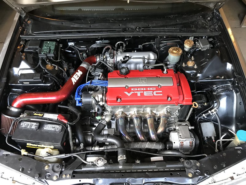
    i did the electro-hydraulic power steering in my cb7 with k24 swap.

    i had the high pressure line made, no issues there. plumbed the return from steering rack back into the ps pump. no issues there.

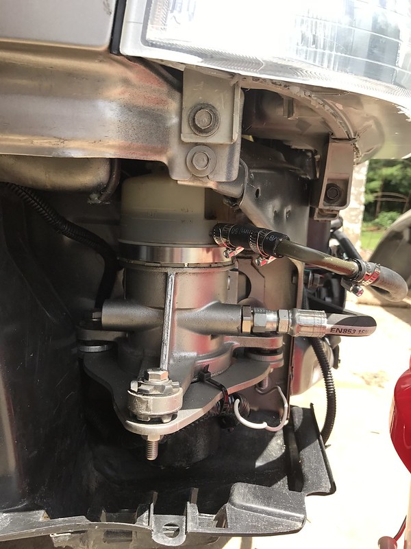
    my problem is the 2 extra ports on the rack. 1 goes to the cooler in the front bumper area, and 1 goes to the vss for variable assist. i have a decent leak from trying to loop those 2 ports together and trying to dump them into the return line.

    what would happen if i blocked those 2 ports off with some plugs? will pressure build up inside the rack? i tried to loop them and as soon as the pump is turned on, the steering wheel when FULL lock to the right and was hard to turn/not safe. trying to find a clean way to eliminate and make my ehps 100% so i can make a diy on it.

    heres a pic showing the port locations.


    any ideas?
    COUPE K24

    #2
    Wish I could help but I plugged all the ports on my rack a long time ago and have not had any power steering. I hope you get a good answer though.
    Turbo H23a3 build has begun
    01-01-2019

    Comment


      #3
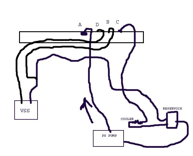
      Sooo here's a drawing I did looking at things from the other way here. But what I don't understand is what way fluids flowing here. B & C are output flow lines I think, but also think of it as fluid escaping the rack & when you turn more fluid is "transferred". Sooo I wouldn't think you could block any of the lines off. You could loop the lines but not cap the rack. I would even think that a small closed loop would have some limitations. ( I could be wrong though)

      Comment


        #4
        Does the k series not have the assist on the vss?

        I’m assuming the fluid would go from (a) to the vss through port (D) then the vss output to the oil cooler from the oil cooler to port (C) then out of the valve chamber through port (B) to the reservoir. But I’m just guessing and that seems like the most logical path.

        So you looped port (C) to (D) and it went full right? I’m trying to think if you blocked those ports if it block the flow and that’s why it went full lock one way as it had no where to flow.

        How do you have it set up right now with it leaking?

        Had to edit some info as I mixed matched the ports. So now this reflects my thoughts.
        Simplified. If I’m a drop of fluid I start at pump go to port (A) then through the port (D) out to VSS. From VSS I go straight to oil cooler. Then back through port (C) into the valve chamber and exit through port (B) to the reservoir.
        Last edited by Grumpys93; 01-06-2019, 11:13 PM.
        ~Nick~
        FSAE (F Series Accord Enthusiasts) ..."A dying breed thats taking it to the next level" Lucky #13
        MR Thread:http://www.cb7tuner.com/vbb/showthre...ight=Grumpys93

        Comment


          #5
          hmmm... lots of good info in here.

          the k series is all electronic. im just trying to figure out how to make a 2 port (in and out) cb7 rack. i guess ill work on how to make my connections better.

          thanks for that pic, it makes it easier to understand how im gonna do it.

          i bought some stainless "t" fittings ill try next.
          COUPE K24

          Comment


            #6
            I think an easy way to figure out how it is all plumbed is get a hand pump and some tubing and connect it to a port and pump the fluid into the chamber and see where it comes out. That will at least give you an idea of where it’s all connected. With the oil cooler line being a lot bigger it makes me think that is a return line from the oil cool and not necessarily an input line going to the oil cooler. But I would have to trace lines to verify that.
            ~Nick~
            FSAE (F Series Accord Enthusiasts) ..."A dying breed thats taking it to the next level" Lucky #13
            MR Thread:http://www.cb7tuner.com/vbb/showthre...ight=Grumpys93

            Comment


              #7
              So, we are utilizing the same setup and I haven't (fingers crossed) encountered any of these issues.

              My car is Euro-R swapped and uses the T2W4 VSS without the VSS feed lines. I used a length of hose to bypass where the lines for the VSS would enter/exit the VSS and used a "T" hose barb where the old reservoir was. The output of the "T" then is plumbed to the input for the MR-S pump.

              Did you take out more of your power steering plumbing when you did the conversion?

              You can see the "T" joint where the Reservoir and the Cruise Control used to be mounted. The high pressure hose follows the routing of the HVAC hoses on the passenger side of the engine bay.

              Last edited by SSMAccord; 01-07-2019, 12:09 AM.
              http://www.hondanews.com/releases/19...d-introduction

              Comment


                #8
                Originally posted by SSMAccord View Post
                So, we are utilizing the same setup and I haven't (fingers crossed) encountered any of these issues.

                My car is Euro-R swapped and uses the T2W4 VSS without the VSS feed lines. I used a length of hose to bypass where the lines for the VSS would enter/exit the VSS and used a "T" hose barb where the old reservoir was. The output of the "T" then is plumbed to the input for the MR-S pump.
                This worked...? Sounds like you are using no reservoir or VSS?

                Comment


                  #9
                  The reservoir MR-S pump is located on the top part of the pump. Looking at the stock configuration, both of the CB lines feed into the reservoir with little to no pressure, I figured that the "T" joint for those 2 lines would follow the path of least resistance and flow back into the pump.

                  I was a little concerned about taking the VSS out of the PS system since I thought it was high pressure, but it hasn't produced any issues.

                  Last edited by SSMAccord; 01-07-2019, 11:21 PM.
                  http://www.hondanews.com/releases/19...d-introduction

                  Comment


                    #10
                    Ya, I'm dying to do what you did there and I'm guessing you did what I did with the mishimoto PS reservoir . Simply T'd (join) the lines going to the old reservoir and send that fluid to the new pump? I read about you using the VSS line but that's the same line, I'm assuming you joined the other 'cooler' line into it as well?

                    & the only high pressure line is the one going to the rack from the pump.

                    Comment


                      #11
                      yea i took every ps line out. but i have another complete line set. i really like what you did with yours. ill probably wind up doing that. looks simple and clean.
                      COUPE K24

                      Comment


                        #12
                        Hmmmm, based on how you described it, it sounds like we merged the same lines. I wouldn't think it mattered where they were joined.

                        Maybe the T fittings will allow the cooler and VSS lines to merge without pressure and eliminate the leak? What fluid are you using in the system, maybe the viscosity is also a factor?
                        http://www.hondanews.com/releases/19...d-introduction

                        Comment


                          #13
                          yea i dont think it matters either. im pretty sure its just leaking because of the clamps/hose i used. im gonna look around for something better.

                          using honda fluid i believe.
                          COUPE K24

                          Comment

                          Working...
                          X