
This is a writeup i did on my home site and figured it would be useful here. Nobody over there corrected anything i had to say so hopefully some one here will notice something and make the information more accurate and useful:
__________________________________________________ _______________________________________________
Ok, this is for those of you who don't know what turbo to use and are always trying to make up your mind. This will tell you the exact turbo/s to use, or at least a very close selection that follow your planned performance. This is currently off the top of my head so when I get my bible back from Justin I'll add to it.
Step One: Getting to know your engine.
Engine CFM (cubic feet per minute) is how much air flows through your engine in a stroke. To figure out how much air moves through your engine, follow this simple equation:
CFM=(CID x RPM x 0.5 x E.v)/1728
CID is cubic inch of displacement. 2L=122 so to translate Liter into CID just multiply Liter by 61 Ex: 1.6L x 61= 97.6CID
The 0.5 is used because only two pistons are vacuuming air at one point in time.
E.v is volumetric efficiency. It is the efficiency that your engine draws in air according to what the laws of physics say. A well designed turbo engine will run at about 85%. So that will be the basis for the simple equations.
1728 is used to translate cubic INCHES into cubic FEET.
So I will use my 2.4L engine as a baseline and I want max power at 7000 RPM.
CFM=(146.4 x 7000 x 0.5 x 0.85)1728= 252CFM
This means that my engine, at 7000 RPM, is vacuuming 252 cubic feet per minute.
Now to apply Boost
1 Bar=14.7lbs of boost. Atmospheric pressure is on average, 1 Bar. So boost is pressure above atmospheric pressure. Lets say I want to increase my engines output by 14.7lbs for simplicity. So now we must find pressure ratio.
PR=(14.7 + boost [in pounds])/14.7. (14.7 + 14.7)/14.7=2 So this means I will be running exactly 2 Bars of boost of absolute pressure, which is actually 1 Bar of Boost at atmospheric pressure.
Now apply boost to CFM and you end up with
252CFM x 2=504CFM at 14.7lbs of boost. Now a good turbo setup for great power and good daily driving the turbo should spool up at roughly 1/3 of the desired RPM range. So for my engine it would be desired for the turbo to spool around 2500RPM. This will be Boost Threshold. So now I must find the flow of air at my boost threshold.
((146.4 x 2500 x 0.5 x 0.85)/1728) x 2)= 179.8 ~180.
Now I must find a turbo that will flow 180CFM to 504CFM at a pressure ratio of 2. Now comes the Turbo Flow Map. I will be using Mitsubishi turbos as a reference mostly for reliability and availability. I will use the popular TD05 16G large wheel AKA �big 16G� and TD05 20G. Now I will apologize for the complication that Mitsubishi maps are usually in Cubic Meters per Second and not the English Cubic Feet per Minute.
CMS~CFM/2100. That�s a rough estimation as exact notation isn�t that important here.
180CFM/2100=0.085CMS 504CFM/2100=0.24CMS
Now how to read a turbo flow map.
A Turbo map shows a turbos efficiency for a certain flow of air across a range of pressure ratios. They also show a few lines from left to right that represent how fast the turbo wheel is spinning. The �bubble� looking lines are efficiency ranges. The middle is the best and highest. the line furthest to the left of the graph is the turbos surge limit. The turbo cannot operate before this line, it can cause dangerous boost spikes. Well how do you determine a turbos efficiency? The laws of thermodynamics say air being compressed to a certain pressure ratio should heat up to a certain temperature. That is in an absolute non existing environment, because the air is affected by outside variables. Air flowing through a turbo is heated even more from the hot metal its inside of and turbulence from the blades. A turbo is put through an extensive test when made to measure the actual heat of the compressed air and compare it to what the laws of thermodynamics say it should actually be. This is the percentage you see on the graph, the actual percent of efficiency, sadly it is always much lower. So the objective is to find a turbo that puts our little flow line, as close to the center as possible. So to begin you take your minimum flow dot which is 0.085 at a pressure ratio of 2, and place it on the graph. Then you take your high flow dot, and do the same. Now draw a line between the two. This represents how your turbo will flow at 14.7lbs of boost from 2500RPM to 7000RPM. Now go to the lower dot and draw a line directly to the left bottom of the graph. This represents the path your turbo will take until the wastegate kicks in. Now these ARE NOT EXACT. Reason being the spring in a wastgate will start releasing pressure before it hits max boost because of pressure building behind it and that in turn cause mild lag. But that�s beside the point right now. This is theory we�re working with. It is best to make sure that your line stay in front of the surge limit, anyway your graph should look like this:
So according to this graph, this turbo would work, but it would really heat up at the higher RPM range, and detonation would be a concern. Also there is not really much room to really turn the boost up. Also you couldnt build that much boost that soon in the RPM range so your a little to close to the surge limit. So now I have gone ahead and plotted our data onto the next turbo, the 20G.
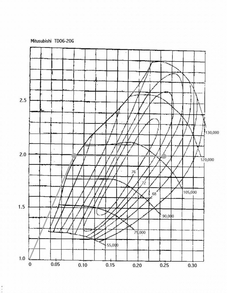
Now our lower point is behind the line, meaning that the turbo will to not spool at 2500 which does not meet the criteria, but considering how well it fit�s the rest of the line, the extra wait climbing the power band will be acceptable. If was really concerned about great really low end power, I might want to find a turbo with a lower surge limit, like for auto-x, but this will do just fine. Our line is almost completely in the middle of the map. This turbo will do perfectly for a daily driven car. By the looks of the graph, I could safely and at a high efficiency run 7lbs all the way to low 20�s and still be in the turbos highest efficiency range.
So you've done some research and you�ve found a few turbos where your flow line is in a great location on the map, how do you decide? For starters, your final decision should be based on the following, which is more reliable, which is more available, price, and preference. Those are my critiques in the order I would use.
This is a webpage that i have found to have find maps for the most popular/common turbos out there. Luckily it also has two conversion tables to help with converting airflow, pressure, and even approximating hp!
http://www.rbracing-rsr.com/turbotech.html
This is how A/R ratio works. Area is area of the turbine scroll. Radius, is the distance from the center of the turbine to the center of the turbine area. A diagram makes it slightly easier to understand.

as you come closer to the smaller part of the scroll, the radius decreases as the ratio decreases, therefore the A/R ratio stays the same.
For two turbos to put out the same CFM, the smaller turbine outlet will have a higher exit velocity and a higher turbine speed. So to consider a turbo with a 3 inch exducer bore the given turbo will have a RPM of 120,000 at a certain CFM. Now for a turbo with a 2 inch exducer bore to flow the same CFM, the turbine wheel will be moving at 160,000. Now obviously the lower turbine speed, the better it is on the turbo. So as a sum, the lower A/R ratio, lets say 0.75 will create a strong low engine speed response, but too low can cause a jumpy spool and fading power in the upper RPMs. Now a higher A/R ration of say 1.5 will create a slower turbine response, but create more power. Too high of an A/R ratio can cause a sluggish spool and the turbo may not even have enough manifold pressure and velocity to create boost. A good spooling turbo that creates good power will generally have an A/R between 1.1 and 1.3. It all depends on your preference of power band and spool time.
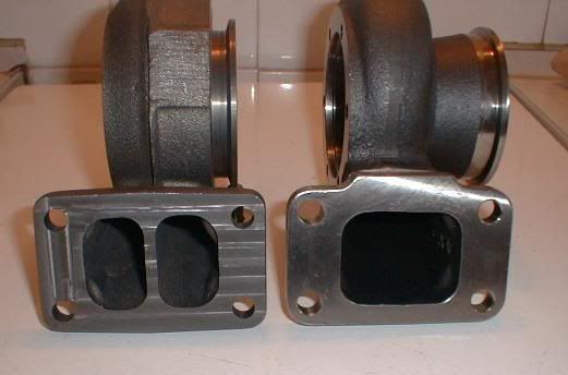
There is also some turbos with a split turbine housing. This is a very good improvement for 4 cylinder engines especially. We�ll call an exhaust pulse a �putt�. So in this case the turbo gets a putt at every 360 degrees of crank rotation. There are 4 cylinders, two fire at every 360 degrees. Now moving exhaust pulses can affect each other and with there only being two puts in a 720 degree rotation (4 cycle engine), the turbo will need all the help it can get and a split housing will separate pulses allowing for better momentum. Now this wouldn't be so useful on a single turbo V8 because there will be a putt every 90 degrees of rotation so the turbo will have a good response.
Not many of us tuners here have to worry about a twin turbo setup, but I might as well write about it. Twin turbos do not reduce lag enough to matter. You have two smaller turbos instead of one big turbo, smaller turbos spool faster than a big turbo, but you are also cutting the pulses in half, therefore having half the power to each turbo. The benefits of a twin turbo design is usually only beneficial in engines with two exhaust banks, or sequential turbos when boost is needed in a large power band. As in an RX-7 TT. A smaller turbo runs at low speeds, then the larger turbo kicks in at higher RPMs. Same thing with a RB26DETT, they wrap up to like 10,000 in some cases. There is also exducer flow efficiency, two turbos with an exducer bore of 2.25 inches will always flow better than one turbo of 3, or even 4 inches. Smaller turbos also mean that boost spikes and turbine wheel speeds are easier to control because each turbo is compressing air a smaller amount than a large turbo would. Lastly and what I believe to be the best reason is that an engine will create a certain amount of heat, absorbed into the turbo/s housing and a certain amount of heat must be created to produce a certain amount of boost. So one turbo will absorb all the heat to produce boost, two turbos will operate at a much lower temperature, sometimes half the temperature, to create the same amount of boost, therefore extending turbine and oil life.
__________________________________________________ _______________
If you want to skip the reading then here's a macro I made. Just list the different values you want for as many situations as you want and I'll put them in, take a screen shot, and post it up here.
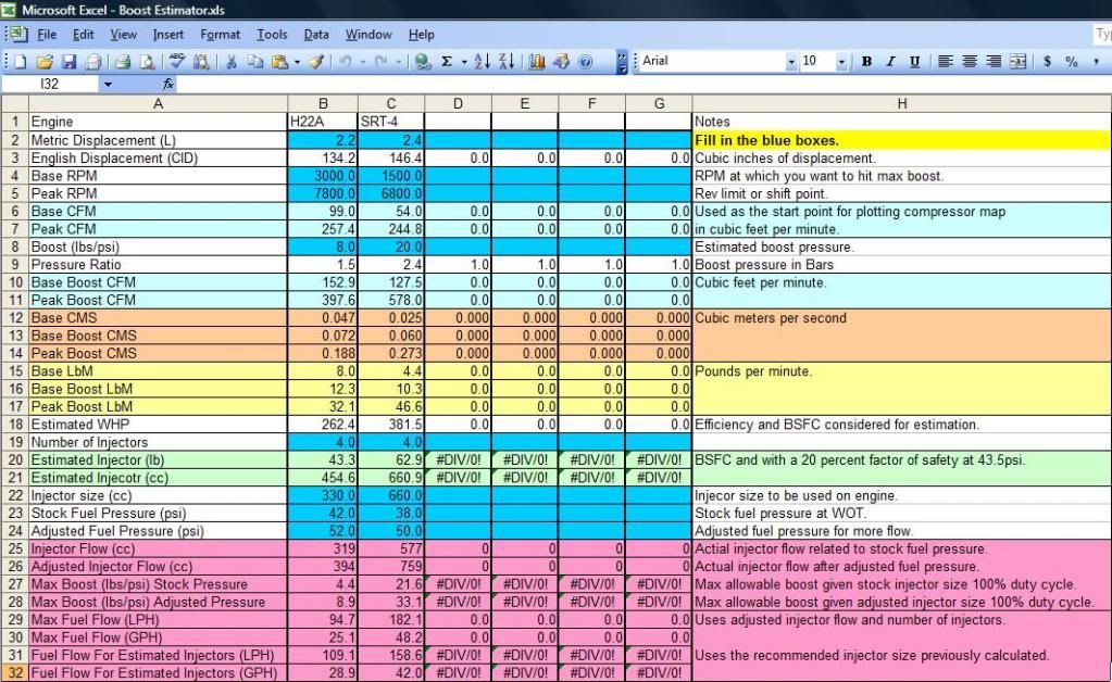
All fuel information is based off an engine that pumps air at an 85% efficiency and is also based of the well accepted relationship between CFM and BSFC. HP is not peak HP, it is HP at that RPM. It is also a low ball meaning actual HP of a well designed system will be at least the same or greater. Remember this is an estimator to give an accurate idea of where your particular values sit. These CFM values are used to compare different compressor maps for your particular needs which is explained in the write ups.
__________________________________________________ _______________________________________________
Ok, this is for those of you who don't know what turbo to use and are always trying to make up your mind. This will tell you the exact turbo/s to use, or at least a very close selection that follow your planned performance. This is currently off the top of my head so when I get my bible back from Justin I'll add to it.
Step One: Getting to know your engine.
Engine CFM (cubic feet per minute) is how much air flows through your engine in a stroke. To figure out how much air moves through your engine, follow this simple equation:
CFM=(CID x RPM x 0.5 x E.v)/1728
CID is cubic inch of displacement. 2L=122 so to translate Liter into CID just multiply Liter by 61 Ex: 1.6L x 61= 97.6CID
The 0.5 is used because only two pistons are vacuuming air at one point in time.
E.v is volumetric efficiency. It is the efficiency that your engine draws in air according to what the laws of physics say. A well designed turbo engine will run at about 85%. So that will be the basis for the simple equations.
1728 is used to translate cubic INCHES into cubic FEET.
So I will use my 2.4L engine as a baseline and I want max power at 7000 RPM.
CFM=(146.4 x 7000 x 0.5 x 0.85)1728= 252CFM
This means that my engine, at 7000 RPM, is vacuuming 252 cubic feet per minute.
Now to apply Boost
1 Bar=14.7lbs of boost. Atmospheric pressure is on average, 1 Bar. So boost is pressure above atmospheric pressure. Lets say I want to increase my engines output by 14.7lbs for simplicity. So now we must find pressure ratio.
PR=(14.7 + boost [in pounds])/14.7. (14.7 + 14.7)/14.7=2 So this means I will be running exactly 2 Bars of boost of absolute pressure, which is actually 1 Bar of Boost at atmospheric pressure.
Now apply boost to CFM and you end up with
252CFM x 2=504CFM at 14.7lbs of boost. Now a good turbo setup for great power and good daily driving the turbo should spool up at roughly 1/3 of the desired RPM range. So for my engine it would be desired for the turbo to spool around 2500RPM. This will be Boost Threshold. So now I must find the flow of air at my boost threshold.
((146.4 x 2500 x 0.5 x 0.85)/1728) x 2)= 179.8 ~180.
Now I must find a turbo that will flow 180CFM to 504CFM at a pressure ratio of 2. Now comes the Turbo Flow Map. I will be using Mitsubishi turbos as a reference mostly for reliability and availability. I will use the popular TD05 16G large wheel AKA �big 16G� and TD05 20G. Now I will apologize for the complication that Mitsubishi maps are usually in Cubic Meters per Second and not the English Cubic Feet per Minute.
CMS~CFM/2100. That�s a rough estimation as exact notation isn�t that important here.
180CFM/2100=0.085CMS 504CFM/2100=0.24CMS
Now how to read a turbo flow map.
A Turbo map shows a turbos efficiency for a certain flow of air across a range of pressure ratios. They also show a few lines from left to right that represent how fast the turbo wheel is spinning. The �bubble� looking lines are efficiency ranges. The middle is the best and highest. the line furthest to the left of the graph is the turbos surge limit. The turbo cannot operate before this line, it can cause dangerous boost spikes. Well how do you determine a turbos efficiency? The laws of thermodynamics say air being compressed to a certain pressure ratio should heat up to a certain temperature. That is in an absolute non existing environment, because the air is affected by outside variables. Air flowing through a turbo is heated even more from the hot metal its inside of and turbulence from the blades. A turbo is put through an extensive test when made to measure the actual heat of the compressed air and compare it to what the laws of thermodynamics say it should actually be. This is the percentage you see on the graph, the actual percent of efficiency, sadly it is always much lower. So the objective is to find a turbo that puts our little flow line, as close to the center as possible. So to begin you take your minimum flow dot which is 0.085 at a pressure ratio of 2, and place it on the graph. Then you take your high flow dot, and do the same. Now draw a line between the two. This represents how your turbo will flow at 14.7lbs of boost from 2500RPM to 7000RPM. Now go to the lower dot and draw a line directly to the left bottom of the graph. This represents the path your turbo will take until the wastegate kicks in. Now these ARE NOT EXACT. Reason being the spring in a wastgate will start releasing pressure before it hits max boost because of pressure building behind it and that in turn cause mild lag. But that�s beside the point right now. This is theory we�re working with. It is best to make sure that your line stay in front of the surge limit, anyway your graph should look like this:
So according to this graph, this turbo would work, but it would really heat up at the higher RPM range, and detonation would be a concern. Also there is not really much room to really turn the boost up. Also you couldnt build that much boost that soon in the RPM range so your a little to close to the surge limit. So now I have gone ahead and plotted our data onto the next turbo, the 20G.
Now our lower point is behind the line, meaning that the turbo will to not spool at 2500 which does not meet the criteria, but considering how well it fit�s the rest of the line, the extra wait climbing the power band will be acceptable. If was really concerned about great really low end power, I might want to find a turbo with a lower surge limit, like for auto-x, but this will do just fine. Our line is almost completely in the middle of the map. This turbo will do perfectly for a daily driven car. By the looks of the graph, I could safely and at a high efficiency run 7lbs all the way to low 20�s and still be in the turbos highest efficiency range.
So you've done some research and you�ve found a few turbos where your flow line is in a great location on the map, how do you decide? For starters, your final decision should be based on the following, which is more reliable, which is more available, price, and preference. Those are my critiques in the order I would use.
This is a webpage that i have found to have find maps for the most popular/common turbos out there. Luckily it also has two conversion tables to help with converting airflow, pressure, and even approximating hp!
http://www.rbracing-rsr.com/turbotech.html
This is how A/R ratio works. Area is area of the turbine scroll. Radius, is the distance from the center of the turbine to the center of the turbine area. A diagram makes it slightly easier to understand.
as you come closer to the smaller part of the scroll, the radius decreases as the ratio decreases, therefore the A/R ratio stays the same.
For two turbos to put out the same CFM, the smaller turbine outlet will have a higher exit velocity and a higher turbine speed. So to consider a turbo with a 3 inch exducer bore the given turbo will have a RPM of 120,000 at a certain CFM. Now for a turbo with a 2 inch exducer bore to flow the same CFM, the turbine wheel will be moving at 160,000. Now obviously the lower turbine speed, the better it is on the turbo. So as a sum, the lower A/R ratio, lets say 0.75 will create a strong low engine speed response, but too low can cause a jumpy spool and fading power in the upper RPMs. Now a higher A/R ration of say 1.5 will create a slower turbine response, but create more power. Too high of an A/R ratio can cause a sluggish spool and the turbo may not even have enough manifold pressure and velocity to create boost. A good spooling turbo that creates good power will generally have an A/R between 1.1 and 1.3. It all depends on your preference of power band and spool time.
There is also some turbos with a split turbine housing. This is a very good improvement for 4 cylinder engines especially. We�ll call an exhaust pulse a �putt�. So in this case the turbo gets a putt at every 360 degrees of crank rotation. There are 4 cylinders, two fire at every 360 degrees. Now moving exhaust pulses can affect each other and with there only being two puts in a 720 degree rotation (4 cycle engine), the turbo will need all the help it can get and a split housing will separate pulses allowing for better momentum. Now this wouldn't be so useful on a single turbo V8 because there will be a putt every 90 degrees of rotation so the turbo will have a good response.
Not many of us tuners here have to worry about a twin turbo setup, but I might as well write about it. Twin turbos do not reduce lag enough to matter. You have two smaller turbos instead of one big turbo, smaller turbos spool faster than a big turbo, but you are also cutting the pulses in half, therefore having half the power to each turbo. The benefits of a twin turbo design is usually only beneficial in engines with two exhaust banks, or sequential turbos when boost is needed in a large power band. As in an RX-7 TT. A smaller turbo runs at low speeds, then the larger turbo kicks in at higher RPMs. Same thing with a RB26DETT, they wrap up to like 10,000 in some cases. There is also exducer flow efficiency, two turbos with an exducer bore of 2.25 inches will always flow better than one turbo of 3, or even 4 inches. Smaller turbos also mean that boost spikes and turbine wheel speeds are easier to control because each turbo is compressing air a smaller amount than a large turbo would. Lastly and what I believe to be the best reason is that an engine will create a certain amount of heat, absorbed into the turbo/s housing and a certain amount of heat must be created to produce a certain amount of boost. So one turbo will absorb all the heat to produce boost, two turbos will operate at a much lower temperature, sometimes half the temperature, to create the same amount of boost, therefore extending turbine and oil life.
__________________________________________________ _______________
If you want to skip the reading then here's a macro I made. Just list the different values you want for as many situations as you want and I'll put them in, take a screen shot, and post it up here.
All fuel information is based off an engine that pumps air at an 85% efficiency and is also based of the well accepted relationship between CFM and BSFC. HP is not peak HP, it is HP at that RPM. It is also a low ball meaning actual HP of a well designed system will be at least the same or greater. Remember this is an estimator to give an accurate idea of where your particular values sit. These CFM values are used to compare different compressor maps for your particular needs which is explained in the write ups.


Comment