I just finished assembling my chip kit from xenocron and I paid extra for a basemap and I told him my engine setup and everything. I added the iab kit because I have an a6 runners and h23 plenum. Put it in fire the car up, Solid CEL, it never turns off once the fuel pump primes. I checked all my solder joints and the socket and all appears well. If I remove the jumper on J1 no check engine light, if I put a wire across the diagnostic connector without the jumper in J1, solid CEL, if I put the jumper in J1 and jumper the diagnostic connector, CEL still stays solid. I'm not sure how much information to include. I tried starting the car with the chip removed just for investigative purposes and it still started up and ran the same as it did initially with the chip installed. This concerns me. I have assembled a megasquirt v3 kit before and the car I built it for started and ran fine my first try so I am not unfamiliar with ecu's, soldering, or troubleshooting. But I don't know where to go from here. I suppose the guy could have taken the $15 for the basemap and Ran figuring I'd never know the difference. I was also worried because the kit I got from xenocron said OBD0 chip kit on the bag, but it had all the parts listed in the description for an obd1 kit. Where should I go from here? I'm lost
Announcement
Collapse
Please DO NOT Post In The General Section
From this point on until otherwise briefed, posting in the general section of Performance Tech is prohibited. The only thing to remain here will be the stickies. We would just delete this section, but that would cause unintended results.
The majority of the threads created can appropriately be placed in one of the Performance Tech sub-forums or Technical; and the posting of them here is detrimental to the activity of said forums. If you have any questions about where you need to place your thread PM me or one of the other mods.
For the most part you all have caught on without this post, but there have been a few habitual offenders that forced me to say this.
Everyone will get a couple of warnings from here on out, after that I just start deleting threads.
Again if you have any questions, PM me or one of the other mods.
See more
See less
p06 chipping, solid CEL competent solder skills, help!
Collapse
X
-
I just noticed that my chip kit didn't come with the 2-0.1uF capacitors that go in c51 and c52... Are these necessary? And why would xenocron sell a chip kit missing that stuff. They come with both moates.net's kit and phearable.net's kits... I feel like this must be my problem and I'll have to order those and wait. Can anyone confirm this?
Comment
-
those are not necessary, they used to be part of the known habitat of a chip kit, but hondata has proven they are not needed.
no, you do not need them.
also, maybe another thing to try is taking the chip out and reinserting it.
you could have mistakenly placed it in the ecu wrong, also ensure all half moon looking shapes on chip and HC373 are facing the appropriate way.
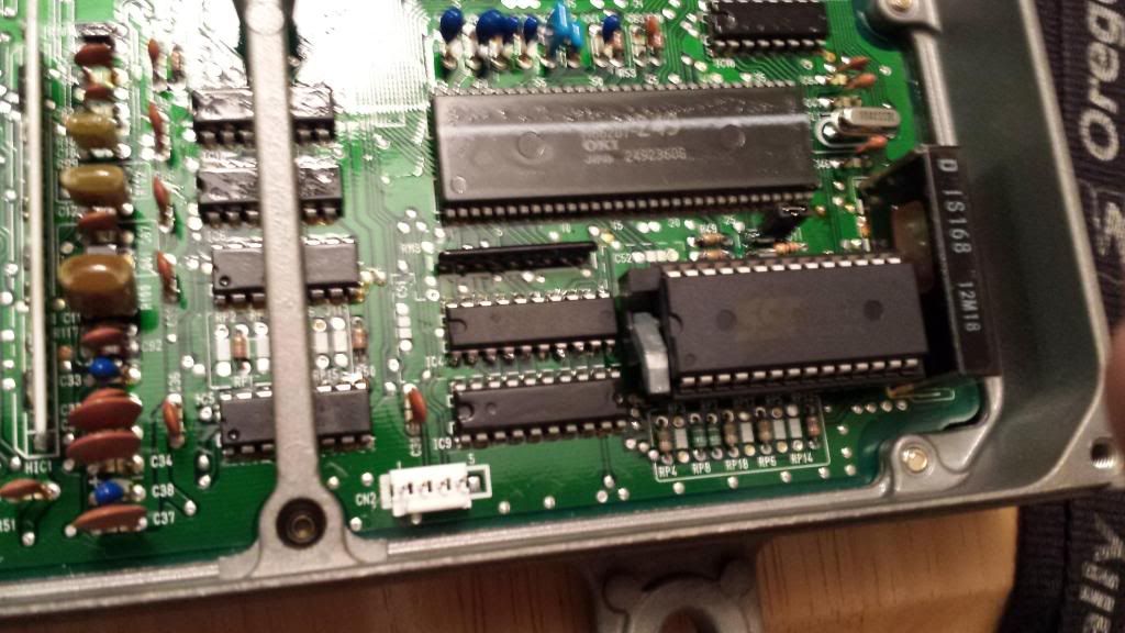
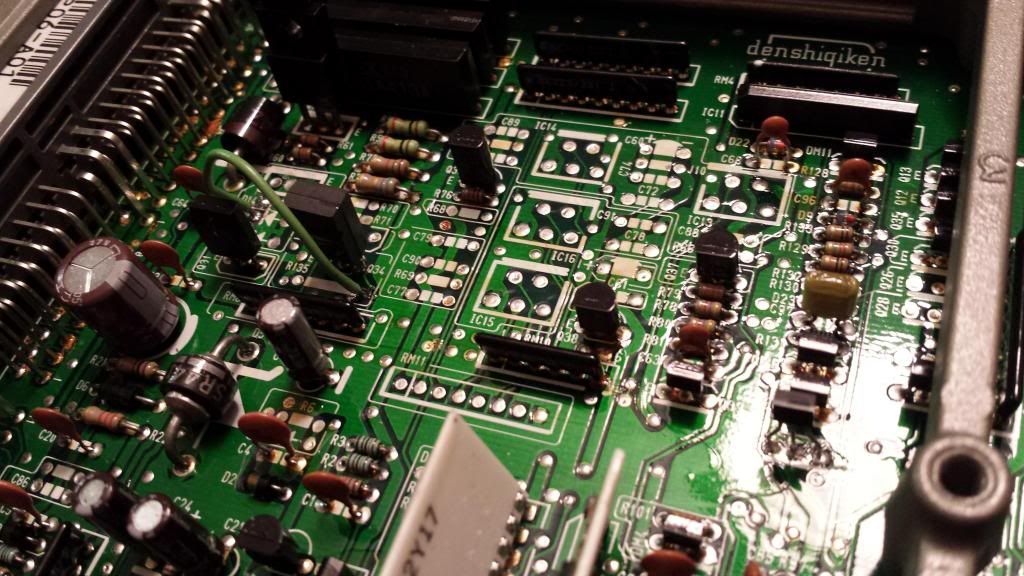
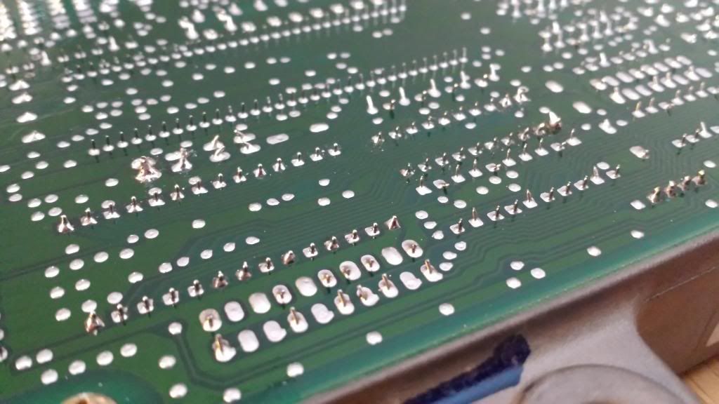
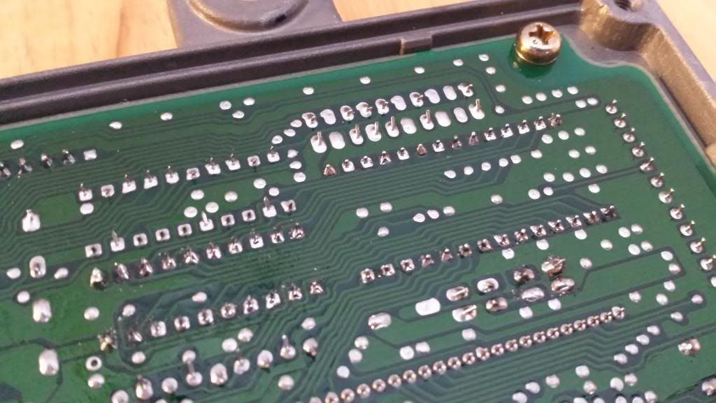
Take a snap shot of your work from upper and lower portions of ecu
and I might be able to tell you whats wrong.
Comment
-
I checked with a voltmeter and checked for continuity between pins on the hc373 chip and there were none that beeped. I know they look ugly but I had a few that were cold joints and I reflowed them from the top. I was using a new soldering iron and was afraid of getting things too hot at first and went too cold on a few of them hence the reflowing but they are all pretty decent except the nasty extra stuff sticking off the hc373.Last edited by DunKrS; 02-13-2014, 12:09 AM.
Comment
-
Desolder the removable jumper,
Do you still have some of the r54 1k resistor
End? I use those, those jumpers they supply
Don't work to well?
The other question being, did you replace
The main capacitor? (Battery)
If that's installed wrong aka positive and negative
Backwards, u get this symptom.
Comment
-
After looking at the pictures I'm going to take a guess that you may have one or more cold solders somewhere. Although you said that you went over everything I would do it again. If the CEL is when you have the jumper installed then it is an issue with the components that you added.
Did you remember to remove the enamel coating from both sides of the board before you started soldering? Also did you use any sort of flux?
The C14 capacitor is installed correctly, can't tell if it is new or original though.
As far as the jumper goes, I would test for continuity in the circuit with the jumper removed. If there is no continuity then there is no reason to remove it.
Wish you were closer, I have a nice little gadget here for testing chipped ECU's. it fits into the 28pin socket and if all is good you get 28 little green lights. If all is not good it will show you what circuit the issue is on. Well worth the money for them. Socket testerLast edited by GhostAccord; 02-13-2014, 11:44 AM.
Comment
-
yes I removed the old c14 and put in a new one. lined up the white mark with the silk screened wedge on the board.
I didn't clean the enamel off but the solder flowed really well and usually it doesn't flow well unless the flux displaces the contaminants effectively in my experience. I have reflowed it and added flux a few times now and it still isn't working. I also removed the components for the iabs to eliminate them from the equation and went over all the joints with rubbing alcohol to clean everything up and then tested for continuity between the edge of the solder joint on the back of the pcb and the legs for both chips on the front side. I may try and get another p06 and move everything over.
I dkd however realize I put the jumper wire for the iabs from the right side of R135 to the arrow side of D14 instead of D13. Maybe I wrecked the chip. I corrected this error with no change and then removed it completely with the rest of the iab parts.Last edited by DunKrS; 02-13-2014, 01:14 PM.
Comment


 [/URL]



Comment