I have this fancy idea floating around in my head and I do believe I've refined it as much as possible before actual implimentation. I want to make a PCB and align LED's behind each and every number on the RPM and Speedometor. Also, do boards for the Temp and Fuel guages with LED's behind each line. The reason I want to do this is for complete and total brightness, crisp clean light, and a "cooler, softer" white. Here is my plans so far.
Make a round PCB with the "Vinyl Sticker" method( http://www.instructables.com/id/Fast...ng-with-Vinyl/ ) to the exact sizes under neath each gauge. Then line each PCB with 5050 3v @ 20mA white LED's(120 degree viewing angle for broad light dispurtion, 10 lumens each) slightly angled so they dont "hot spot" on the face. Use Acetone to gently remove the film on thee back of the guages to allow for color to easily pass through.
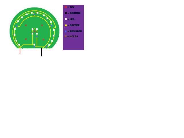
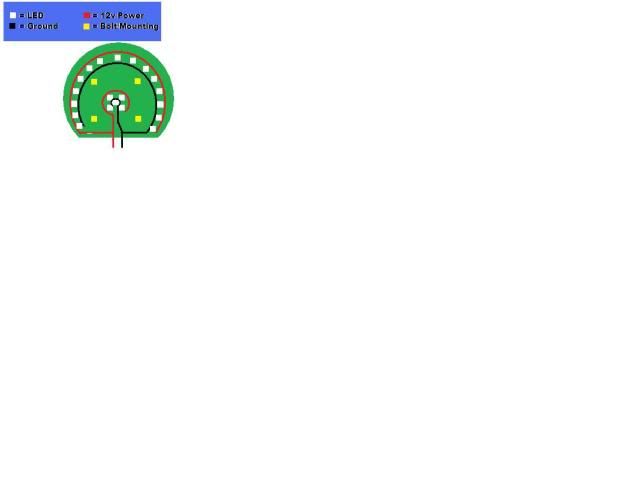
Now my question is this(more so for the LED man himself, DEEVERGOTE), if I wired 17 LED's up in 4 parralel series of 4 LED's each(one random LED to light up MPH), shouldnt the load/current be just fine to run them? Here is a crude MS Paint drawing for the Speedo portion:

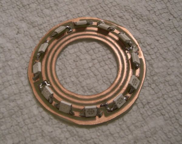
The reason why I'm doing it this was is because after some trial and error on a DIY desktop power inverter, I couldnt get more then 5 LED's to light up on a single 12v source when wired completely in parralel. Example:

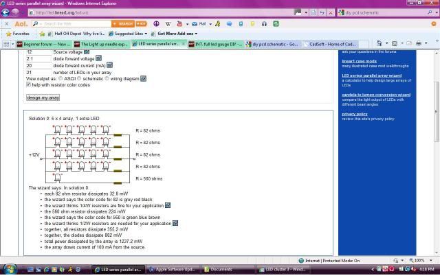
So after some googling(is that even a word?), I came accross this LED array wizard. With the inputs I currently have, this is the array it gave me:

I can continue trial and error on the desktop inverter but it quickly trying my patience.... Any other ideas?
Btw, this is what the end result I am hoping for(Blackrex's design btw):

Make a round PCB with the "Vinyl Sticker" method( http://www.instructables.com/id/Fast...ng-with-Vinyl/ ) to the exact sizes under neath each gauge. Then line each PCB with 5050 3v @ 20mA white LED's(120 degree viewing angle for broad light dispurtion, 10 lumens each) slightly angled so they dont "hot spot" on the face. Use Acetone to gently remove the film on thee back of the guages to allow for color to easily pass through.
Now my question is this(more so for the LED man himself, DEEVERGOTE), if I wired 17 LED's up in 4 parralel series of 4 LED's each(one random LED to light up MPH), shouldnt the load/current be just fine to run them? Here is a crude MS Paint drawing for the Speedo portion:

The reason why I'm doing it this was is because after some trial and error on a DIY desktop power inverter, I couldnt get more then 5 LED's to light up on a single 12v source when wired completely in parralel. Example:

So after some googling(is that even a word?), I came accross this LED array wizard. With the inputs I currently have, this is the array it gave me:

I can continue trial and error on the desktop inverter but it quickly trying my patience.... Any other ideas?
Btw, this is what the end result I am hoping for(Blackrex's design btw):

