Announcement

Collapse
No announcement yet.

COP Retrofit Thread

Collapse
X
 
  • Filter
  • Time
  • Show
Clear All
new posts

    COP Retrofit Thread

    This thread is a spin-off from the other one:
    http://www.cb7tuner.com/vbb/showthread.php?t=209326

    Here will be the portion on how to, theoretically, replace the stock dizzy with a homebrew COP setup. When I get my Lude up and running, I'll have another rolling laboratory again and the ability to test these theories...eventually. For now, this is an online notepad for me

    YouTube Clicky!!

    #2
    How does the ECU know when to fire the spark and in what order?

    There are three sensors that most Hondas use to determine the crankshaft position. These are the CKP, TDC, and CYP variable-reluctance (VR), more commonly known as magnetic, sensors. From Delphi's site: "Delphi Variable Reluctance Sensor consists of a permanent magnet surrounded by a winding of wire and, for application flexibility, it can be used in conjunction with a ferrous target that has either notches or teeth."
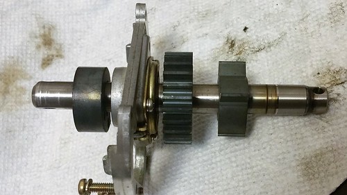
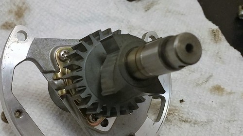
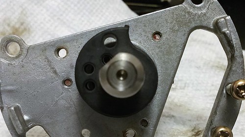
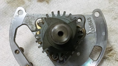
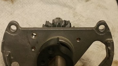
    In the CB these ferrous targets are located within the distributor housing and look like this:


    The wheels on the distributor shaft are the ferrous targets. Ferrous simply means that it is attracted to a magnet.


    The TDC sensor. The Top-Dead-Center sensor is a 4-tooth wheel with a ramp type of cut. Remember our term "variable" reluctance? The reluctance varies with proximity to the pickup, which simply means that the closer the wheel's protrusions are to the sensor, the higher the output voltage. The shape of the wheel affects how the output waveform "looks." Also, the faster the wheel turns, the higher the sensor's output voltage. Our ECU has built in compensation for the changing output voltage.

    The tips at the end of the ramp, the flat part is the actual tooth. These are spaced 90 degrees apart, just like our distributor points! The Top-Dead-Center of the TDC sensor teeth isn't the exact Top-Dead-Center of the piston that each tooth represents. When you adjust for timing by rotating the distributor these points are set to 14-16 BTDC for stock timing. The problem here is that we can't tell which TDC sensor tooth represents which cylinder yet! That leads me to the next sensor which is...


    The CYP sensor. The CYlinder Position sensor is 45 degrees behind the TDC for Cylinder #1. This is a ramped 1-tooth wheel. This sensor is how the ECU knows when to start the 1-3-4-2 firing pattern. It's the reset signal, the repeat sign, etc. This is the electrical equivalent of our distributor rotor returning back to Cylinder #1 just to go around in a circle again. This reset signal is very important for my idea of a simple COP control.


    The CKP sensor. The CranKshaft Position sensor is the 24 tooth, straight cut wheel. 24 teeth/4 = 6 teeth per 90 degree section. There is a 360/24=15 degree separation between each tooth. I'm pretty sure that the ECU calculates the majority of the fuel and ignition timing with this sensor, probably more so engine speed than anything else.


    Now the cool thing about this sensor is that it is perfectly aligned with the 1-tooth CYP sensor. The ECU could count 1,2,3,4,5,6 teeth and fire the next cylinder in the sequence.

    I had a few questions initially:
    How can the ECU accurately adjust timing in between those 15 degree tooth segments?Probably calculates timing based on engine speed, and just looks up the timing tables.

    If the ECU can just count the number of CKP sensor teeth between each firing, then what is the TDC sensor for?
    The TDC sensor kind of gives a 14-16 degrees advanced notice of the piston position. This advanced notice plus engine speed gives the ECU enough time to calculate when to fire the spark.
    Last edited by sonikaccord; 09-10-2017, 08:02 PM.

    YouTube Clicky!!

    Comment


      #3
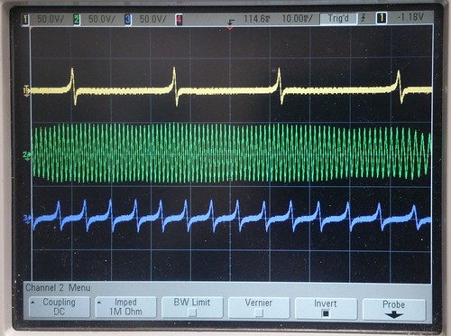
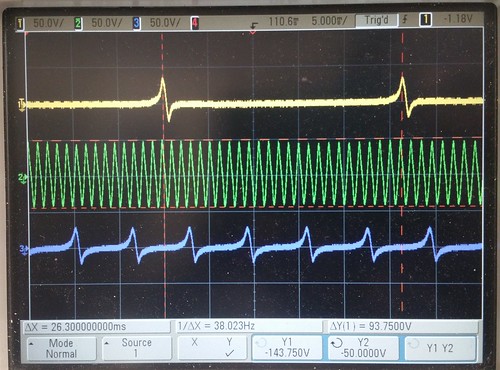
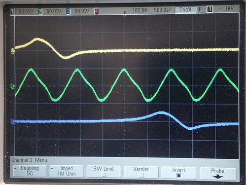
      These are the actual synced outputs from all three sensors CYP at the top, CKP in the middle, TDC at the bottom


      Found a nice PDF file:
      http://www.flw.com/pdf/airpax.pdf

      From here, it appears that a cam (TDC and CYP ramp) actually reduces the voltage swing in the opposite direction. Meaning, if a cammed gear swings up, then the swing back down would not be as high. I have verified this with the oscilloscope. Look how the CKP wave is pretty symmetrical. It is not cammed and swings about 45V in both directions. The CYP swings up about 35V and only swings down to -20V. The TDC swings up to about 28V and swings down to -21V. I'm sure the ECU doesn't see voltages this high, but because the sensors are open ended (technically 1Mohm because of my scope probe) it will appear very high.

      Found some more smart guys:
      http://rusefi.com/forum/viewtopic.ph...450fd6ebbc5963
      http://forum.pgmfi.org/viewtopic.php...15570&start=45
      http://rusefi.com/wiki/index.php?title=Hardware:MAX232

      People from both of those forums have had success with the Maxim MAX232 IC to reproduce the VR output signals from square wave inputs. A few key points that I gleaned:
      I found that all three(sensor outputs) go into the perpendicular daughterboard (not the one directly next to J12, but the other one). The purpose of this board is to turn the zero crossing variable reluctor signals into nice clean 5V square waves that the processor can use.
      the circuit is designed to compensate for amplitude increases as a function of frequency. Therefore the higher the frequency input, the higher amplitude the circuit requires to still produce an output.
      The MAX232 gave me a 17V peak to peak wave and I can now crank the RPM up to 8000 with no dropped teeth.
      I traced the VR signal through the ECU until it hit the board that actually turns it into the 0-5V wave. Then I probed every connection on the board until I found the corresponding TTL level signal. I noticed that when I didn't apply a waveform, this line sits at 5V. For me that's enough to say that it (in all likelihood) triggers on a negative slope. However, it is very possible that the board actually inverts the signal. I don't remember at this moment if the OBD I ECU actually did this, but it is very possible.
      "i wonder if it's possible to send a direct input to those board connections through a buffer and bypass the VR board completely."
      I'm sure of it.

      When I couldn't get the amplitude I needed out of my "sinusoid" I thought about doing just that...

      For the record, I do think that a 0-12V square wave passed through series capacitor would have probably worked. I haven't tested it or anything, but I'm fairly confident that it would've worked just fine instead of the MAX232.
      Before you get too brainiac about this, it pays to examine what the "detector" circuitry is inside the ECU. In almost all cases, VR sensor interfaces boil down to zero-crossing detectors that trigger on either the rising or falling edge of the zero crossing. (This is why polarity DOES matter with VR sensors! Their signal waveform is inverted when the wires are reversed, which almost always skews the expected zero crossing point.) ((I'm sure Jared or one of the "real" EEs can chime in and fill in some blanks here))

      So... With that said. What do you need to generate to please a VR sensor interface?
      1. Positive voltage swing with reference to gnd
      2. SHARP downswing
      3. Zero crossing
      4. Negative voltage swing with respect to gnd
      5. return to resting (gnd) state
      6. (HARD) Varying amplitude with respect to RPM - more RPM, greater amplitude of signal

      In practice, if you can achieve #1-#5, you can typically fool almost all VR detectors. Only relatively new ECUs are going to be smart enough to even try to monitor the peak voltages with respect to RPM.
      Super ghetto: use MAX232, hook outputs together (with current limiting resistor), hook inputs to 2x GPIO pins (possibly attached to a hardware timer?), run signals inverted ( 0 1 ) to produce opposite outputs i.e. "gnd" or resting state, drive both pins 0 or 1 to produce high/low swings. I've tested this approach to 12,000 RPM with a 24 tooth wheel pattern and it produces reliable enough signals to fool a Honda and Toyota ECU.

      Less ghetto: create a -voltage supply, use 3 GPIO pins. One FET to control +V, one FET to control -V, one FET to control pull to GND.
      Last edited by sonikaccord; 09-10-2017, 08:04 PM.

      YouTube Clicky!!

      Comment


        #4
        I think it's possible to digitally distribute our ECUs ignition output. That would eliminate the need to figure out Honda's timing protocol, allow us to keep the stock sensors and still eliminate the high tension portion of the distributor.

        The only downside of the digital distributor, is that we would be stuck with the dwell time that the ECU calculates.

        We would also need to know when to digitally "shift" to the next coil. I have an idea of a very simple circuit to accomplish this. I'll do a napkin plan for that.

        YouTube Clicky!!

        Comment


          #5
          a lot of great info in this thread!
          COUPE K24

          Comment


            #6
            I had typed up a nice overview of the circuit, but it was lost when I hit send. Let's try this again.

            I have the circuit drawn up in my head and have the components on paper. Without going into too much detail, here is how it's going to work...hopefully.

            There will be two input signals and four output signals. The inputs will be the CYP signal and the ECU signal to the ICM(igniter) which I will call the Coil signal. The outputs will be the Coil signal delivered to its respective igniter. Oh yeah, I forgot to mention for prototyping, I'll be grabbing some coils and igniters from the junkyard. Here is a teaser, the stock ICM is a monster of a transistor/switch...with a proper heatsink it can handle massive current and has NO built in dwell limiter like some other COP systems.

            Continuing, the CYP signal is going to tell the circuit to start back over at 1...well technically 0. That is its only job. The Coil signal, the signal that our ECU would normally just give to our igniter in the distributor is, itself, going to be distributed to one of our 4 igniters. Pretty much instead of distributing 20,000+ volts in a rotating device, we are going to be distributing 12v and 5v in a solid state circuit with no moving parts.

            The Coil signal is going to tell the circuit to transition to the next igniter, before the next Coil signal is even sent. There is black magic in this black box that I'm making.

            The Coil signal will also inhibit the circuit from firing any unwanted coils.

            All this from only 4 ICs and some transistors...no processor involved yet. If this goes well, I may consider it. That would allow us to do some math on the Coil signal and manipulate ignition timing without chipping the ECU. And it could be programmed via Bluetooth from your Android and/or iOS device. I'm just rambling now, but you all get the idea. I'll be back with a physical circuit, or at least some measurements.

            YouTube Clicky!!

            Comment


              #7
              I have some Denso coils off a Scion you can barrow if you need for testing, man. Good stuff

              Comment


                #8
                Originally posted by F22Chris View Post
                I have some Denso coils off a Scion you can barrow if you need for testing, man. Good stuff
                Thanks man! I posted in the wrong thread again. lol
                Last edited by sonikaccord; 06-12-2017, 05:38 PM.

                YouTube Clicky!!

                Comment

                Working...
                X