I was really bored today, so I decided to install a switch on the Service Check Connector (CEL plug). First of all, I did not come up with this idea myself. I was "inspired" by cp[mike] in a post about reading CEL codes, but I thought I would do it a little bit different.
I wouldn't exactly label this DIY as a must do, but since I am periodically getting codes and performing maintenance which requires the circuit to be shorted, I decided that this would be a convenient addition to the car.
Parts List:
-------Necessary Parts----------
1 x Male 2-pin connector (Radio Shack #274-154, $1.99)
1 x Female 2-pin connector (Radio Shack #274-151, $1.99)
1 x On/Off switch (Radio Shack #275-730, $2.99)
2 x 1/4" Female quick disconnects (Radio Shack# 64-3133, $1.69)
1 x 6" piece of ~14 gauge dual strand wire (speaker wire will work fine)
--------Optional Parts----------------
(1) x 3x5 photo paper
(1) x Piece of laminating paper
Tools list:
Fine point Sharpie
Dremmel
Dremmel cutting wheel
Dremmel soft metal cutting bit (looks like a wood router bit, but made for metal)
Dremmel diamond embedded grinding bit
Wire cutters
Wire crimpers
Procedure:
Step 1. Remove the kick plate that covers the SCC (Service Check Connector or CEL Plug, whatever you call it).
Step 2. Using the mounting bracket supplied with the switch (#275-730), trace the inside of the hole onto the car frame using a fine point Sharpie. Center the hole as close as you can.
Note: On the bracket, there is a decorative "lip" around the top edge. I ground this down so that the bracket would sit flush against the frame for better tracing.
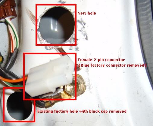
Cut out the traced hole, and don't forget to cut a notch (look at the switch!)
Step 3. Remove the black hole cap located just below the new hole. Cut a small hole in the cap to allow the wire to pass through.
Step 4. Cut off the existing blue SCC, and install the female 2-pin connector (#274-151) in its place.

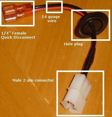
Step 5. Assemble the connecting wire by attaching the male 2-pin connector (#274-154) to one end. Pass the wire through the black hole cap. The male 2-pin connector should be exiting out from the cap when installed. (In other words, when the black cap is reinstalled, the 2-pin connector should be sticking out, and the two quick disconnects should be inside the frame). Then attach 2 female quick disconnects(#64-3133) to the other end of the wire.

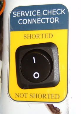
Step 6. (Optional) Install SCC label on frame.
Step 7. Pass connecting wire in from the lower existing factory hole up to and out of the newly cut hole. Ensure that the black cap is properly installed as it was before removal.
Step 8. Ensure the hole is cut to the correct size. Connect the switch to the 2 quick disconnects and install switch into the newly cut hole.
Step 9. Connect the male and female 2-pin connectors.

The kick plate reinstalls perfectly without any interference. Now you can read codes or make adjustments with the flip of a switch!
The final result came out really well with the exception of the switch being slight tilted. I guess I was a little of when I notched the hole. Oh well, at least it works!
Tips on the label: I created the label using MS Word. I printed it on Photo paper to give it "real" look. Before cutting it out, I covered it with laminating paper to protect it (just in case). I cut a hole (using the bracket as a template again) and stuck to the frame using Elmers Glue!
If anyone wants the label, it is attached below.
Let me know what you guys think.
I wouldn't exactly label this DIY as a must do, but since I am periodically getting codes and performing maintenance which requires the circuit to be shorted, I decided that this would be a convenient addition to the car.
Parts List:
-------Necessary Parts----------
1 x Male 2-pin connector (Radio Shack #274-154, $1.99)
1 x Female 2-pin connector (Radio Shack #274-151, $1.99)
1 x On/Off switch (Radio Shack #275-730, $2.99)
2 x 1/4" Female quick disconnects (Radio Shack# 64-3133, $1.69)
1 x 6" piece of ~14 gauge dual strand wire (speaker wire will work fine)
--------Optional Parts----------------
(1) x 3x5 photo paper
(1) x Piece of laminating paper
Tools list:
Fine point Sharpie
Dremmel
Dremmel cutting wheel
Dremmel soft metal cutting bit (looks like a wood router bit, but made for metal)
Dremmel diamond embedded grinding bit
Wire cutters
Wire crimpers
Procedure:
Step 1. Remove the kick plate that covers the SCC (Service Check Connector or CEL Plug, whatever you call it).
Step 2. Using the mounting bracket supplied with the switch (#275-730), trace the inside of the hole onto the car frame using a fine point Sharpie. Center the hole as close as you can.
Note: On the bracket, there is a decorative "lip" around the top edge. I ground this down so that the bracket would sit flush against the frame for better tracing.
Cut out the traced hole, and don't forget to cut a notch (look at the switch!)
Step 3. Remove the black hole cap located just below the new hole. Cut a small hole in the cap to allow the wire to pass through.
Step 4. Cut off the existing blue SCC, and install the female 2-pin connector (#274-151) in its place.

Step 5. Assemble the connecting wire by attaching the male 2-pin connector (#274-154) to one end. Pass the wire through the black hole cap. The male 2-pin connector should be exiting out from the cap when installed. (In other words, when the black cap is reinstalled, the 2-pin connector should be sticking out, and the two quick disconnects should be inside the frame). Then attach 2 female quick disconnects(#64-3133) to the other end of the wire.

Step 6. (Optional) Install SCC label on frame.
Step 7. Pass connecting wire in from the lower existing factory hole up to and out of the newly cut hole. Ensure that the black cap is properly installed as it was before removal.
Step 8. Ensure the hole is cut to the correct size. Connect the switch to the 2 quick disconnects and install switch into the newly cut hole.
Step 9. Connect the male and female 2-pin connectors.

The kick plate reinstalls perfectly without any interference. Now you can read codes or make adjustments with the flip of a switch!
The final result came out really well with the exception of the switch being slight tilted. I guess I was a little of when I notched the hole. Oh well, at least it works!
Tips on the label: I created the label using MS Word. I printed it on Photo paper to give it "real" look. Before cutting it out, I covered it with laminating paper to protect it (just in case). I cut a hole (using the bracket as a template again) and stuck to the frame using Elmers Glue!
If anyone wants the label, it is attached below.
Let me know what you guys think.


 )
)


Comment